Configuring / Programming
9.3 Inserting and configuring M-Bus devices
PN/M-Bus LINK
Operating Instructions, 03/2018, A5E44260928-AA
39
Creating additional M-Bus devices
You can create additional M-Bus devices as required.
e a maximum of 40 M-Bus device modules from the hardware catalog.
Empty slots between filled slots are not used for communication but still count.
The setting of the input values in case of a module failure is a fixed value that cannot be
changed.
Figure 9-3 Module failure
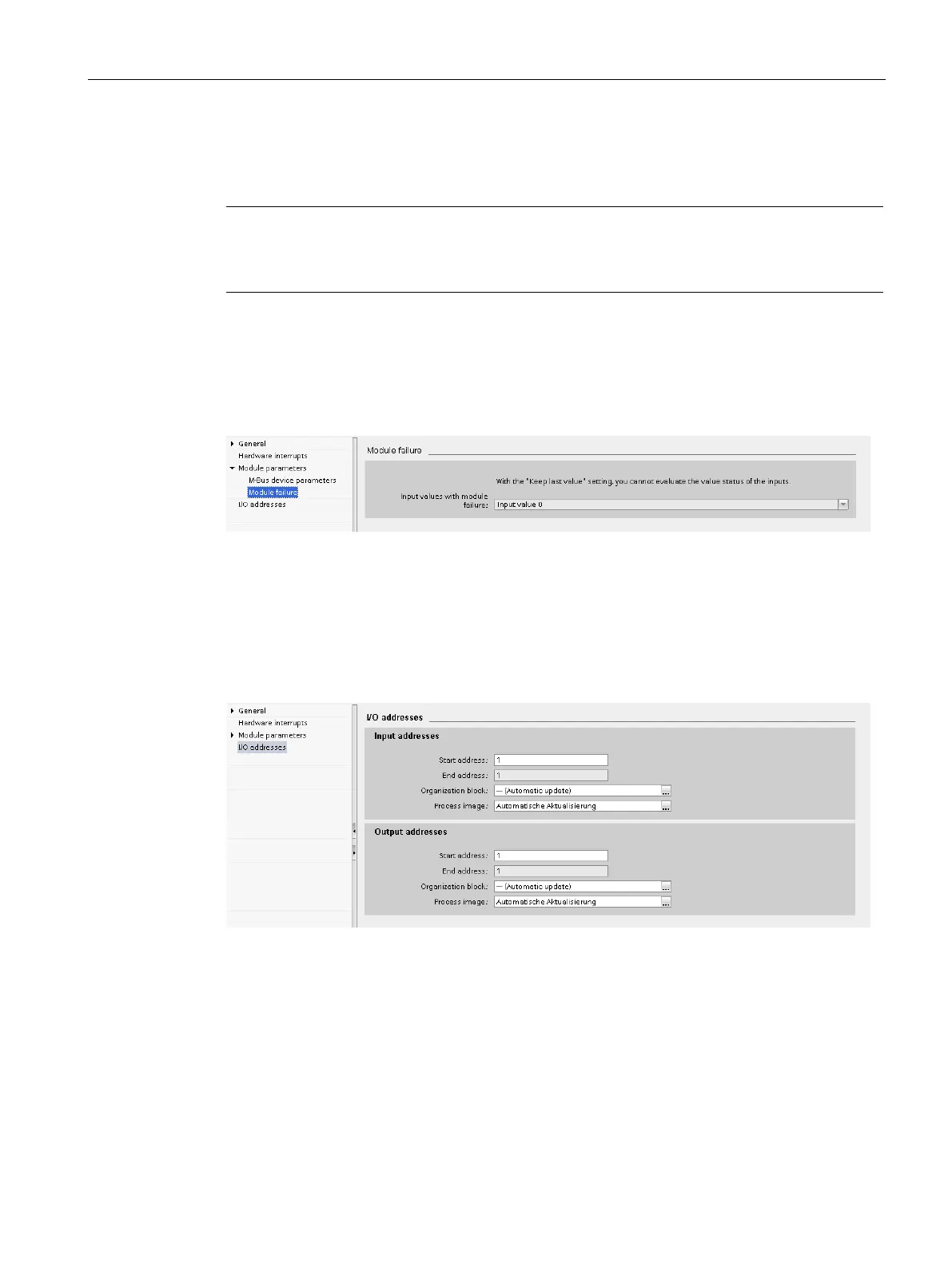
On the "I/O addresses" page, you can check and set the start and end addresses of the
input and output data for the M-Bus device. In addition, the address range can be assigned
to an organization block and a process image. I/O addresses are preset by the system.
Figure 9-4 Adapting I/O addresses
 Loading...