Quick review
1.2 From schematic diagram to user program
Getting started with S7-1200
Getting Started, 11/2009, A5E02486791-01
13
1.2 From schematic diagram to user program
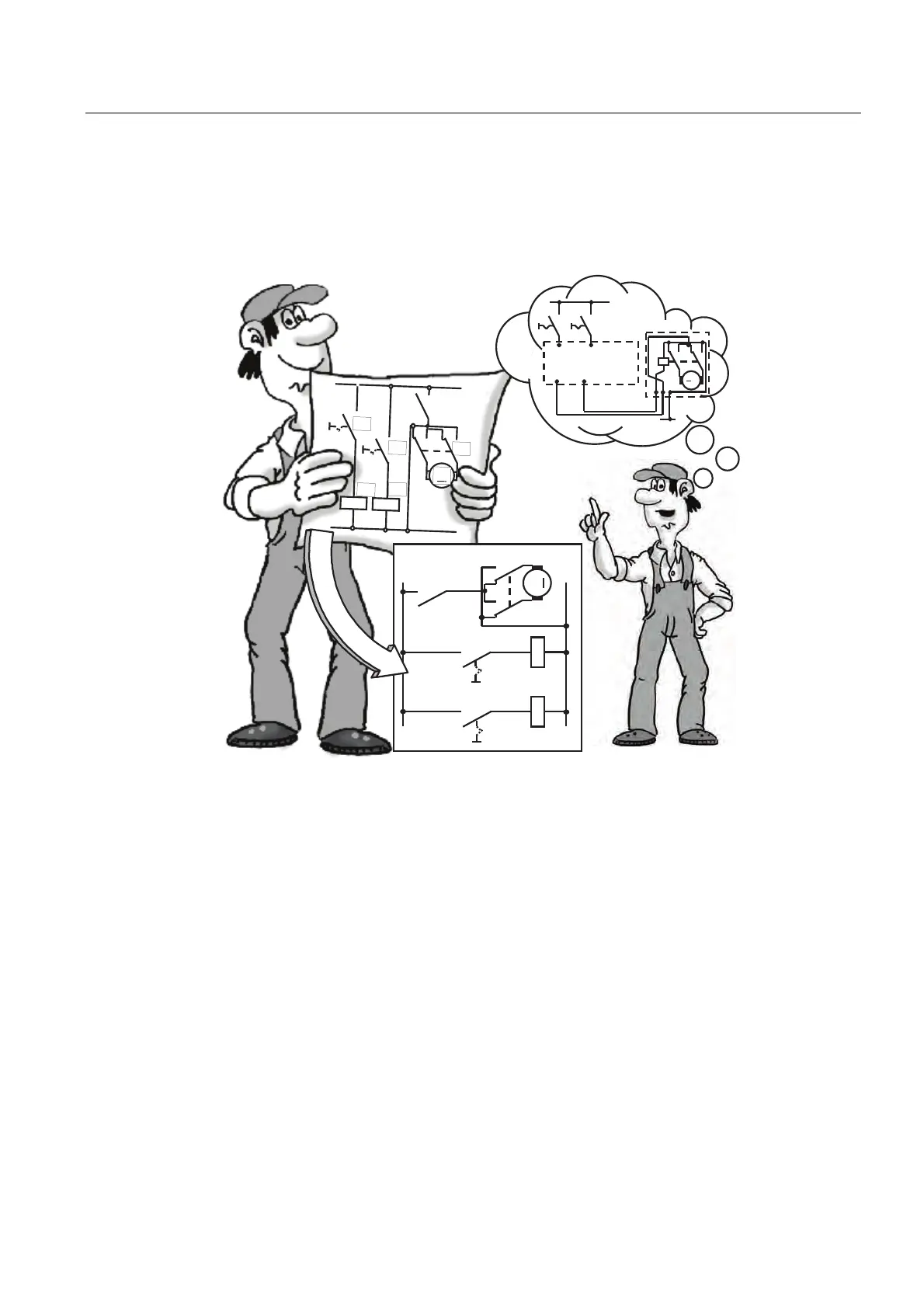
To transform a circuit diagram into a PLC program, simply rotate your circuit diagram 90° to
the left. Your power rail then appears on the left, with the grounding rail on the right. The
switching elements of your circuit appear in the middle.
.
0
6 6
, ,
44
6
.
.
0
6
.
.
6
6
.
.
.
0
.
6
The circuit logic of a machine (such as time relays or flip-flops) which used to be
implemented by wiring together switches, auxiliary contactors or control contactors is now
handled by the PLC. The control elements on the input side (such as input switches or
selector switches) and the power contactors on the output side (such as motor contactors,
polarity reversers, or valves) cannot be replaced by the PLC.

 Loading...


