Quick review
1.2 From schematic diagram to user program
Getting started with S7-1200
16 Getting Started, 11/2009, A5E02486791-01
1.2.2 Basic electrical circuits
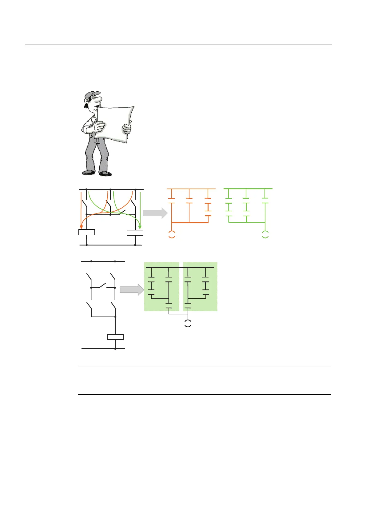
If you are changing over from contactor technology to PLC
technology you will probably encounter switch combinations that
cannot be converted directly into ladder diagram representation.
(To aid in the comparison, the LAD networks have been arranged
vertically.)
Bridge circuits: The following figure shows a simple bridge circuit (on
the left). You use two LAD networks to implement the simple bridge
circuit, as shown on the right. Each network handles one of the two
possible current paths of the bridge circuit.
D
E
F
G
)
(
)
(
DEF DEF
GGG
)
DE
F
G
H
)
D
E
F
G
H
D
E
F
As shown here, you can also have a
complex bridge circuit.
The first network corresponds to the
"a-c-parallel-b" path. The second
network corresponds to the "b-c-
parallel-a" path.
Note
In new projects, avoid using the bridge circuit in the circuit diagram where possible! Think "in
LAD" right from the start!

 Loading...


