Quick review
1.2 From schematic diagram to user program
Getting started with S7-1200
14 Getting Started, 11/2009, A5E02486791-01
1.2.1 Converting the schematic to LAD instructions
.
3%
3%
.
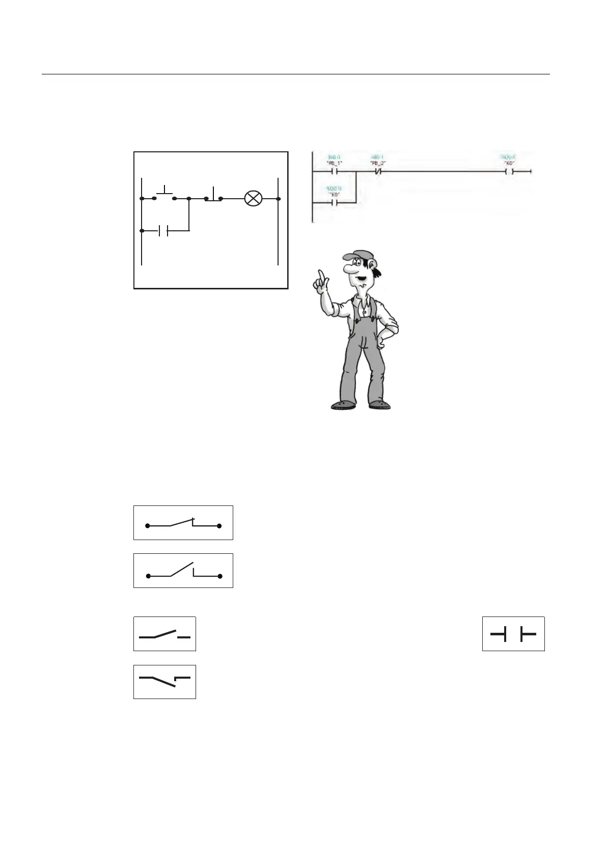
Let’s have a closer look at
the structure of the PLC
program in a ladder diagram
(LAD).
This type of representation
closely resembles a circuit
diagram.
Digital control logic uses only 0 and 1 for the data states. The "0" state equates to a "false"
condition, and the "1" state equates to a "true" condition. In an electrical circuit, current flow
determines the binary state: Current flow equals 1, and no current flow equals 0. At the
beginning of every scan, the CPU stores the states of the inputs as either 0 (false) or 1
(true).
A closed switch allows current flow. In this case, the state of the
circuit equals "1".
"1" = "True" = Current flow
An open switch does not allow current flow. In this case, the
state of the circuit equals "0".
"0" = "False" = No current flow
Specific LAD instructions correspond to basic electrical circuits of the schematic diagram.
Positive logic for the input sensor scan ("normally open
contact"):
24V = high-level = "1"
0V = low-level = "0"
Is current flowing? If yes, then the result of the scan is
"true" (or "1").

 Loading...


