Quick review
1.2 From schematic diagram to user program
Getting started with S7-1200
Getting Started, 11/2009, A5E02486791-01
15
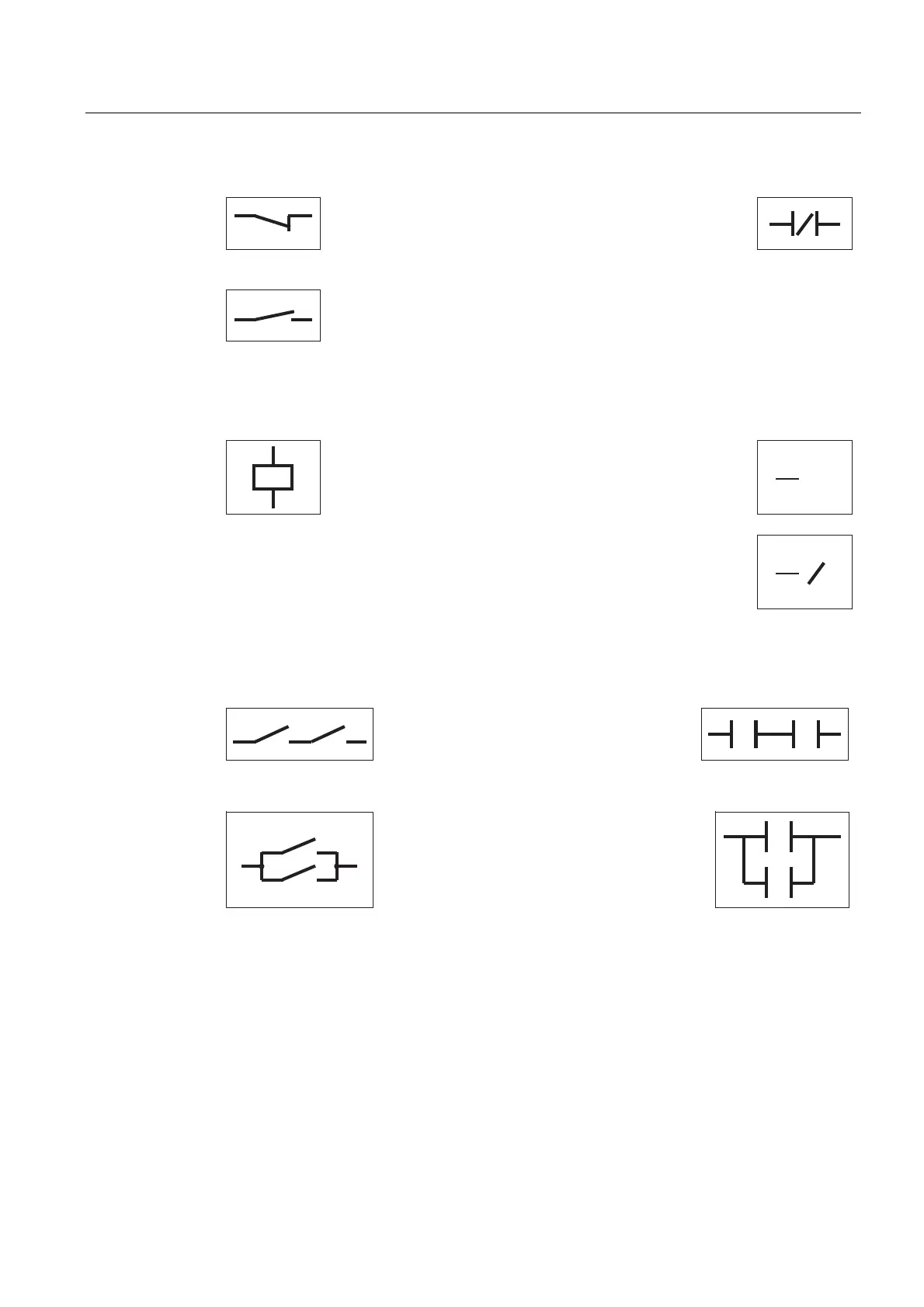
Negative logic for the input sensor scan ("normally closed
contact"):
0V = low-level = "1"
24V = high-level = "0"
Is current flowing? When there is no current flowing through the physical
contact, then the result of the scan is "true" (or "1"). Power flow then
passes through the LAD contact.
Remember that there is no current when the contact is closed because this is the "normal"
condition. When the contact is actuated, it then opens and signals that the contact is active
Output coil: If the value "true" (current or "power flow") is
passed to the coil, the CPU activates the coil by turning the
coil on (set to "1").
()
You can insert an output coil in the middle of a network, not only at the end.
In addition, the CPU supports a negated coil that reflects the inverse of the
power flow to that coil.
()
You combine electrical circuits to perform logic operations. For example, a serial
connection of two contacts creates an AND operation for two inputs.
The first switch AND the second switch
must be closed in order to pass current.
You represent the AND operation in LAD
by combining two instructions in sequence.
For OR logic, you use a parallel connection of two contacts.
Either the first switch OR the second switch
must be closed in order to pass current. To
create a parallel circuit connection (OR
logic), you create a branch in the LAD
network.

 Loading...


