Installation
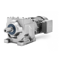
4.5 Gearbox with flange fastening
BA 2030
Operating Instructions, 02/2021, A5E37880173A/RS-AM
33
4.5 Gearbox with flange fastening
AG recommends an anaerobic adhesive to enhance the friction lock between flange
Table 4- 3 Thread size of the fastening bolt
Thread
size
Flange
Helical gearbox
Parallel shaft
Bevel gearbox
Helical worm
Use screws / nuts of strength class 8.8 for gearboxes with a flange-mounted design.
Note the following exceptions:
Table 4- 4 Strength class of the fastening bolt for FF/FAF and KF/KAF
Gearbox
size
Flange
Strength class for motor size