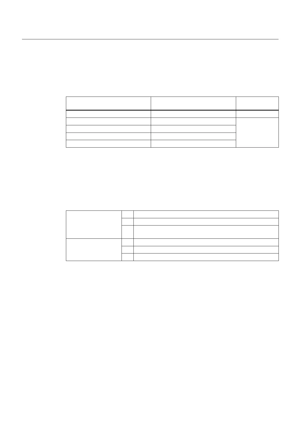
Limit values for the stator winding insulation resistance
The following table specifies the measuring voltage and limit values for the insulation
resistance. These values correspond to IEEE 43‑2000 recommendations.
Table 5-1 Stator winding insulation resistance at 40° C
U
N
V
U
meas
V
R
C
MΩ
U ≤ 1000 500 ≥ 5
1000 ≤ U ≤ 2500 500 (max. 1000) 100
2500 < U ≤ 5000 1000 (max. 2500)
5000 < U ≤ 12000 2500 (max. 5000)
U > 12000 5000 (max. 10000)
U
rated
= rated voltage, see the rating plate
U
meas
= DC measuring voltage
R
C
= minimum insulation resistance at a reference temperature of 40 °C
Conversion to the reference temperature
When measuring with winding temperatures other than 40° C, convert the measuring value to
the reference temperature of 40° C according to the following equations from IEEE 43-2000.
(1)
R
C
=
K
T
·
R
T
R
C
Insulation resistance converted to 40° C reference temperature
K
T
Temperature coefficient according to equation (2)
R
T
Measured insulation resistance for measuring/winding temperature
T
in °C
(2)
K
T
= (0.5)
(40-T)/10
40 Reference temperature in °C
10 Halving/doubling of the insulation resistance with 10 K
T
Measuring/winding temperature in °C
In this case, doubling or halving the insulation resistance at a temperature change of 10 K is
used as the basis.
● The insulation resistance halves every time the temperature rises by 10 K.
● The resistance doubles every time the temperature falls by 10 K.
Assembly
5.1 Preparations for installation
SIMOTICS HV C 1NB1402-2AA84-4CA0-Z
42 Operating Instructions 06/2018