Direction of rotation
If the machine has one shaft extension or two shaft extensions with different diameters, the
direction of rotation when looking at the front of the single or the thicker shaft extension is
defined as follows:
● If you connect line cables with a phase sequence of L1, L2, L3 at U, V, W, the resulting
rotation is clockwise.
● If you interchange two connections, e.g. you connect L1, L2, L3 to V, U, W, the resulting
rotation will be counter-clockwise.
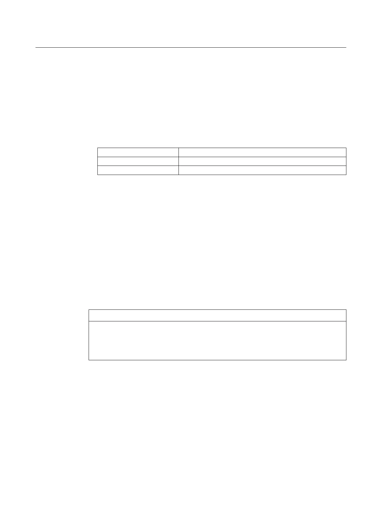
According to IEC
Clockwise U V W
Counter-clockwise V U W
Direction of rotation of the motor when looking at DE
Machines that must run only in one specific direction of rotation are marked as follows.
– On the rating plate with a direction of rotation arrow
– With terminal designations in the required phase sequence
The machine can malfunction or be damaged if it is operated other than how it was originally
ordered or with the incorrect direction of rotation.
Changing the direction of rotation
If you want to operate the machine in the opposite direction to the direction stated in the order,
please consult your contact partner at Siemens.
Directions of rotation, which may be required for an application in a particular plant or system,
are not shown on the rating plate. Please take these requirements into consideration when
connecting up the machine.
NOTICE
Machine damage due to incorrect direction of rotation
The machine will not be adequately cooled if it is operated other than how it was originally
ordered or with the incorrect direction of rotation. This can result in machine damage.
● Observe the direction of rotation data on the nameplate.
6.3.2 Tightening torques for cable glands
● Tighten the cable gland and the parts of terminal box intended to act as a strain relief to
the appropriate torque as specified by the manufacturer after inserting the feeder cables.
The tightening torques depend on the cable gland used and the cable or wire used.
● Tighten the standard cable glands supplied with the motor in accordance with the following
table.
Electrical connection
6.3 Inserting and routing the cables
SIMOTICS HV C 1NB1402-2AA84-4CA0-Z
Operating Instructions 06/2018 61