EasyManuals Logo

Siemens SIMOTICS S-1FT7 User Manual

Siemens SIMOTICS S-1FT7
408 pages
To Next Page IconTo Next Page
To Previous Page IconTo Previous Page
Page #380 background imageLoading...
Page #380 background image
Electrical connection
8.3 System integration
S-1FT7 synchronous motors
378 Configuration Manual, 09/2018, A5E45099423B AA
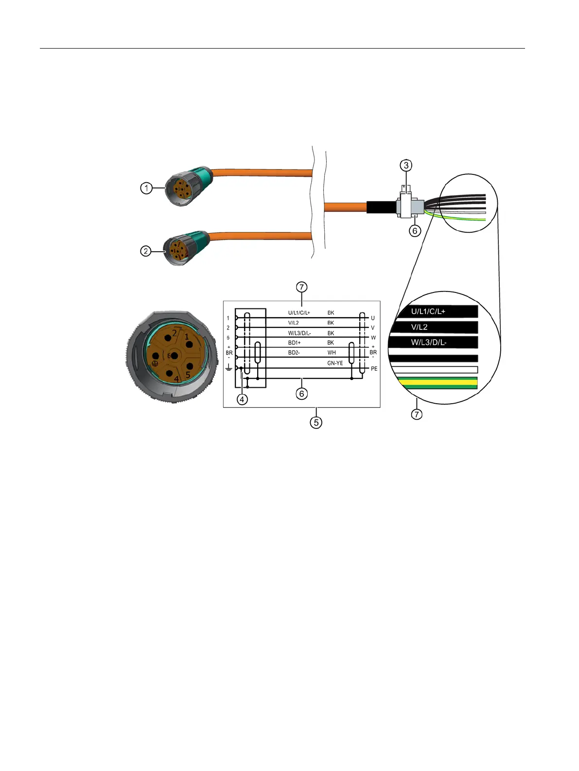
Connection diagram for the motor to the S120 Power Module and Motor Module Booksize
and Compact with a MOTION-CONNECT cable
For connector size M23
1
Connector size M23
2
Connector SPEED-CONNECT M23
3
Terminal for the cable shield
4
Pin assignment
5
Circuit diagram
6
Cable shield
7 Conductor designation:
U, V, W = power cables, 1.5 mm
2
, each cable separately shielded
BD1+ and BD2- = brake cable without lettering, 1.5 mm
2
, shared shield
PE = protective conductor

Table of Contents

Questions and Answers:

Question and Answer IconNeed help?

Do you have a question about the Siemens SIMOTICS S-1FT7 and is the answer not in the manual?

Siemens SIMOTICS S-1FT7 Specifications

General IconGeneral
BrandSiemens
ModelSIMOTICS S-1FT7
CategoryEngine
LanguageEnglish

Related product manuals