Electrical connection
8.3 System integration
S-1FT7 synchronous motors
380 Configuration Manual, 09/2018, A5E45099423B AA
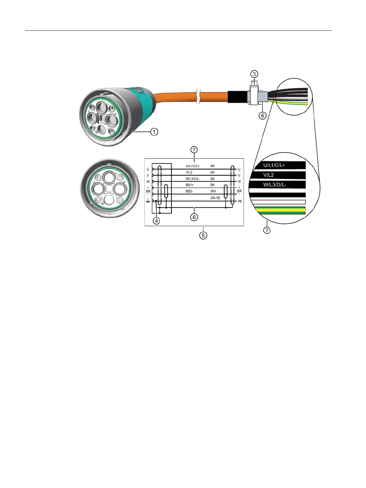
For connector size M58
Terminal for the cable shield
7 Conductor designation:
U; V; W = power cables, each cable separately shielded
BD1+ and BD2- = brake cable without lettering, 1.5 mm
2
, shared shield
PE = protective conductor
● Connect the shield at both ends at the motor and at the converter.
● Keep unshielded cable ends as short as possible.
● To ensure good conducting of high-frequency currents, provide contacting over a large
surface area. Use EMC cable glands at the cable entries as 360° contacts on the
converter, for example.