Fundamental Principles and System Description
Engineering Information
SINAMICS Engineering Manual – November 2015
Ó Siemens AG
128/528
The following tables provide guide values for the theoretically attainable contribution of individual S120 Basic Line
Modules, Smart Line Modules, Active Line Modules and individual S120 Motor Modules to the total peak short-circuit
current I
peak short-circuit total
on the DC busbar.
When only a few Line Modules and Motor Modules are connected to the DC busbar, the table values are relatively
precise so that the values stated for individual Line Modules and Motor Modules can simply be added in order to
calculate the total peak short-circuit current. As the number of Line Modules and Motor Modules connected to the DC
busbar increases, the average distance between individual S120 Modules and the short-circuit location – and thus
also the relevant inductance – increases with the result that the total peak short-circuit current decreases. When
calculating the total peak short-circuit current, it is possible to make allowance for this effect by applying the
correction factor k which is dependent on the number of Line Modules and Motor Modules connected to the DC
busbar. The approximate total peak short-circuit current on the DC busbar is therefore
I
peak short-circuit total
= k∙[sum of the peak short-circuit currents of all Line Modules and all Motor Modules……..
……..on the DC busbar according to tables]
The following applies to factor k:
o Number of Line Modules and Motor Modules < 10 k = 1.00
o Number of Line Modules and Motor Modules 10 - 20 k = 0.75
o Number of Line Modules and Motor Modules > 20 k = 0.50
With parallel connections comprising several S120 Line Modules or several S120 Motor Modules, each component of
the relevant parallel connection must be taken into account individually. In the case of a triple parallel connection of
Line Modules and a triple parallel connection of Motor Modules on one DC busbar, for example, a total of 6 Modules
needs to be included.
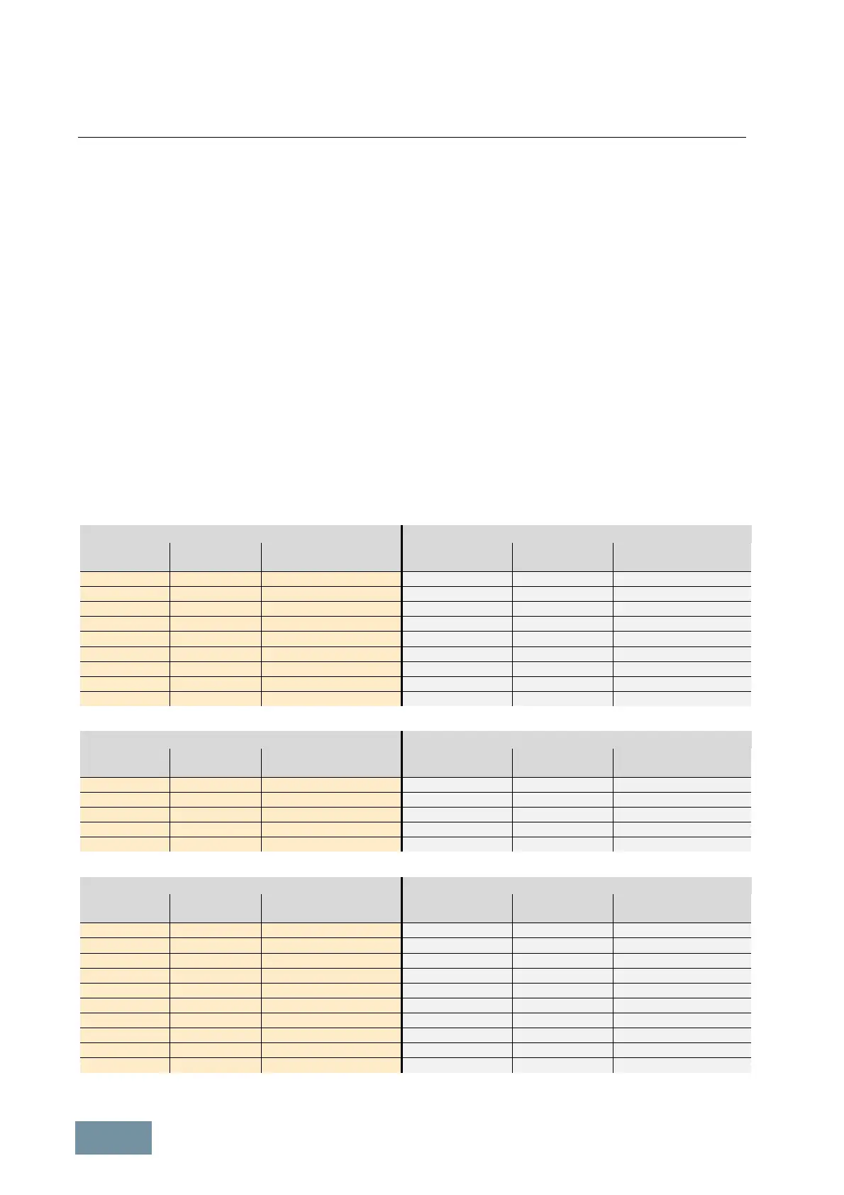
Basic Line Modules 380 V to 480 V 3AC Basic Line Modules 500 V to 690 V 3AC
Power
[ kW ]
Frame size Peak short-circuit current
[ kA ]
Power
[ kW ]
Frame size Peak short-circuit current
[ kA ]
200
FB 3.3
250
FB 4.5
250
FB 4.2
355
FB/FBL 6.4
360
FBL 6.0
560
FB 10.1
400
FB 6.7
630
FBL 11.3
560
GB 9.4
900
GB 16.2
600
FBL 10.0
1100
GB/GBL 19.8
710
GB 11.9
1370
GBL 24.7
830
GBL 13.9
1500
GD 27.0
900
GD 15.0
Contribution of individual S120 Basic Line Modules to the total short-circuit current on the DC busbar
Smart Line Modules 380 V to 480 V 3AC Smart Line Modules 500 V to 690 V 3AC
Power
[ kW ]
Frame size Peak short-circuit current
[ kA ]
Power
[ kW ]
Frame size Peak short-circuit current
[ kA ]
250
GX 4.2
450
GX 8.1
355
GX 5.9
710
HX 12.8
500
HX 8.4
1000
JX 18.0
630
JX 10.5
1400
JX 25.2
800
JX 13.4
-
- -
Contribution of individual S120 Smart Line Modules to the total short-circuit current on the DC busbar
Active Line Modules 380 V to 480 V 3AC Active Line Modules 500 V to 690 V 3AC
Power
[ kW ]
Frame size Peak short-circuit current
[ kA ]
Power
[ kW ]
Frame size Peak short-circuit current
[ kA ]
132
FX 2.2
630
HX / HXL 11.3
160
FX 2.7
800
JX / JXL 14.4
235
GX 3.9
900
HXL 16.2
300
GX / GXL 5.0
1100
JX / JXL 19.8
380
HX / HXL 6.3
1400
JX / JXL 25.2
450
HX 7.5
1700
JXL 30.6
500
HX / HXL 8.4
-
- -
630
JX / JXL 10.5
-
- -
800
JX 13.4
-
- -
900
JX / JXL 15.0
-
- -
Contribution of individual S120 Active Line Modules to the total short-circuit current on the DC busbar

 Loading...


