SINAMICS G150
Engineering Information
SINAMICS Engineering Manual – November 2015
Ó Siemens AG
311/528
5.4 Cable cross-sections and connections on SINAMICS G150 Cabinet Units
5.4.1 Recommended and max. possible cable cross-sections for line and motor connections
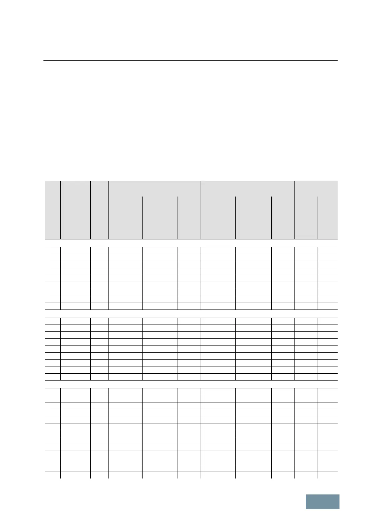
The tables below list the recommended and the maximum connectable cable cross-sections on the line and motor
sides for single converters (versions A and C) and for parallel connections of converters (version A). The
recommended cross-sections are based on the fuses specified in catalog D 11. These are valid for PVC-insulated,
copper 3-wire cables installed horizontally in air with a permissible conductor temperature of 70 °C (e.g. Protodur
NYY or NYCWY) at an ambient temperature of 40 °C and for singly routed cables. When the conditions differ from
the above stated (cable routing, cable grouping, ambient temperature), the relevant correction factors as stated in
IEC 60364-5-52 must be applied.
When aluminum cables are used, the recommended cross-sections given in the table must be increased by a factor
of 1.3. This can be done either by enlarging the conductor cross-section or by increasing the number of parallel
cables. It is important to note, however, that the cable cross-sections must not exceed the specified maximum
permissible dimensions at the converter and must be suitable for connection to the motor terminal box.
Single converters G150 Version A
Out-
put
[kW]
Converter
SINAMICS
G150
Version A
Type
6SL3710-…
Weight
(stan-
dard
model)
[kg]
Line supply connection Motor connection Cabinet
grounding
Recom
cross-section
1)
IEC
[mm
2
]
Maximum cable
cross-section
M12
fixing
screw
(no. of
holes)
Recommended
cross-section
1)
IEC
[mm
2
]
Maximum cable
cross-section
screw
(no. of
holes)
screw
(no. of
holes)
Re-
marks
IEC
[mm
2
]
IEC
[mm
2
]
380 V – 480 V 3AC
110 1GE32-1AA3 320 2x70 4x240 (2) 2x50 2x150 (2) (2)
132 1GE32-6AA3 320 2x95 4x240 (2) 2x70 2x150 (2) (2)
160 1GE33-1AA3 390 2x120 4x240 (2) 2x95 2x150 (2) (2)
200 1GE33-8AA3 480 2x120 4x240 (2) 2x95 2x150 (2) (2)
250 1GE35-0AA3 480 2x185 4x240 (2) 2x150 2x240 (2) (2)
315 1GE36-1AA3 860 2x240 4x240 (2) 2x185 4x240 (2) (2)
400 1GE37-5AA3 865 3x185 4x240 (2) 2x240 4x240 (2) (10) Busbar
450 1GE38-4AA3 1075 4x150 8x240 (4) 3x185 4x240 (2) (16) Busbar
560 1GE41-0AA3 1360 4x185 8x240 (4) 4x185 6x240 (3) (18) Busbar
500 V – 600 V 3AC
110 1GF31-8AA3 390 120 4x240 (2) 95 2x150 (2) (2)
132 1GF32-2AA3 390 2x70 4x240 (2) 120 2x150 (2) (2)
160 1GF32-6AA3 390 2x95 4x240 (2) 2x70 2x185 (2) (2)
200 1GF33-3AA3 390 2x120 4x240 (2) 2x95 2x240 (2) (2)
250 1GF34-1AA3 860 2x185 4x240 (2) 2x120 4x240 (2) (2)
315 1GF34-7AA3 860 2x185 4x240 (2) 2x150 4x240 (2) (2)
400 1GF35-8AA3 865 2x240 4x240 (2) 2x185 4x240 (2) (2)
500 1GF37-4AA3 1320 3x185 8x240 (4) 2x240 6x240 (3) (18) Busbar
560 1GF38-1AA3 1360 4x150 8x240 (4) 3x185 6x240 (3) (18) Busbar
660 V – 690 V 3AC
75 1GH28-5AA3 320 50 4x240 (2) 35 2x70 (2) (2)
90 1GH31-0AA3 320 50 4x240 (2) 50 2x150 (2) (2)
110 1GH31-2AA3 320 70 4x240 (2) 70 2x150 (2) (2)
132 1GH31-5AA3 320 95 4x240 (2) 70 2x150 (2) (2)
160 1GH31-8AA3 390 120 4x240 (2) 95 2x150 (2) (2)
200 1GH32-2AA3 390 2x70 4x240 (2) 120 2x150 (2) (2)
250 1GH32-6AA3 390 2x95 4x240 (2) 2x70 2x185 (2) (2)
315 1GH33-3AA3 390 2x120 4x240 (2) 2x95 2x240 (2) (2)
400 1GH34-1AA3 860 2x185 4x240 (2) 2x120 4x240 (2) (2)
450 1GH34-7AA3 860 2x185 4x240 (2) 2x150 4x240 (2) (2)
560 1GH35-8AA3 860 2x240 4x240 (2) 2x185 4x240 (2) (2)
710 1GH37-4AA3 1320 3x185 8x240 (4) 3x150 6x240 (3) (18) Busbar
800 1GH38-1AA3 1360 4x150 8x240 (4) 3x185 6x240 (3) (18) Busbar

 Loading...


