EMC Installation Guideline
Engineering Information
SINAMICS Engineering Manual – November 2015
Ó Siemens AG
246/528
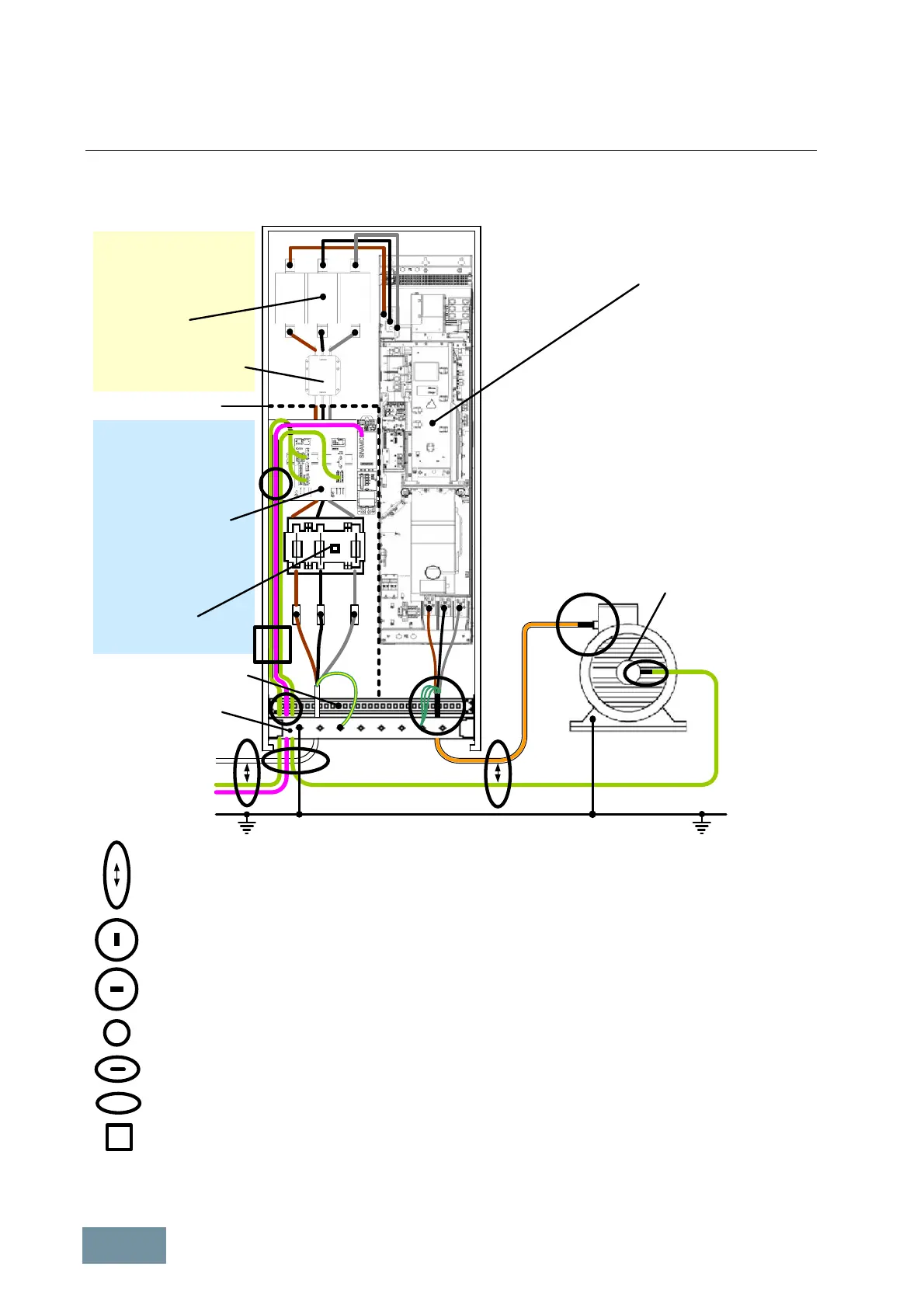
2.4.7.2 EMC-compliant construction/installation of a cabinet with a SINAMICS G130 Chassis unit
Supply system cable
(unshielded)
Signal cable
and bus cable
(shielded)
Encoder cable
(shielded)
Minimum distance between power cables and signal cables: 20 cm to 30 cm
Shield bonding of the motor cable in the converter on an EMC shield busbar using EMC shield
clips and connection of the three symmetrical PE conductors on the PE busbar
Shield bonding of the motor cable on the motor terminal box using EMC cable glands
Shield bonding of the signal, bus, and encoder cables
Shield bonding of the encoder cable on the housing of the speed encoder
Signal, bus, and encoder cables in the converter must be routed as close as possible
to the cabinet frame or on grounded plates at a large distance from the power cables
Motor
PE-busbar
EMC shield busbar
Speed encoder
SINAMICS G130 chassis unit
Separation plate
Line reactor
Line filter ( optional )
acc. to Category C2
Area of filtered supply
system cables acc. to
Category C3
Area of filtered supply
system cables acc. to
Categorie C2
Mounting plate for:
- Terminal Module
- Sensor Module
- Control Unit
Fuse
disconnector
Motor cable
(shielded)
Power cables and signal cables cross at an angle of 90°

 Loading...


