SINAMICS S120
Engineering Information
SINAMICS Engineering Manual – November 2015
Ó Siemens AG
380/528
6.10 Checking the total cable length for multi-motor drives
In the case of SINAMICS S120 multi-motor drives, the total cable length (i.e. the sum of the motor cable lengths for
all the Motor Modules that are fed by a common Infeed Module and via a common DC busbar) must be restricted.
This is necessary in order to ensure that the resulting total capacitive leakage current Σ I
Leak
(sum of the capacitive
leakage currents I
Leak
generated from the individual Motor Modules 1…n), which depends on the overall motor cable
length, does not overload the Infeed Module if this current flows back to the DC busbar via the line filter of the Infeed
Module or via the supply system, and the Infeed Module itself.
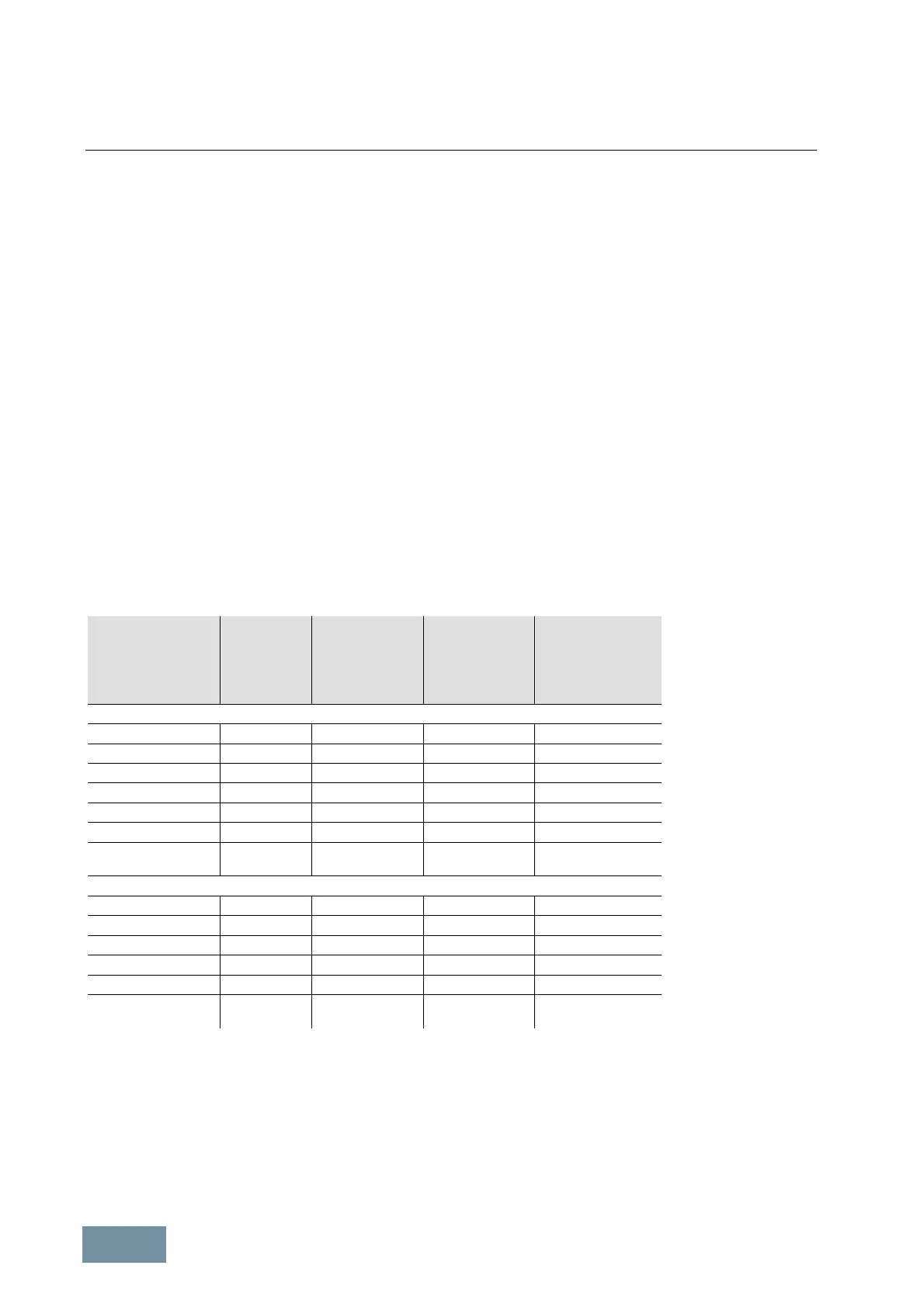
The following table specifies the values for the permissible total cable length l
perm
for the various types of SINAMICS
S120 Infeed Modules when feeding multi-motor drives. The following must be noted here:
· The total cable length l
perm
is the cable length that is really routed. This means in the case of drives which
have higher output currents and more than one motor cable routed in parallel, that each of the parallel
cables must be taken into account when the total cable length is calculated.
· The total cable length l
perm
applies to shielded motor cables. In the case of unshielded motor cables, values
1.5 times higher are permissible.
· When S120 Infeed Modules are connected in parallel, the specified permissible total cable length l
perm
must be
multiplied by the number of Infeed Modules connected in parallel. A derating of 7.5% must be observed for
Basic Line Modules and Smart Line Modules, and a derating of 5% for Active Line Modules.
· The values apply regardless of the type of supply system, i.e. for both grounded TN supply systems and
non-grounded IT supply systems.
SINAMICS S120
Infeed Module
Frame size Rated power at
400 V / 690 V
[ kW ]
Input current at
400 V / 690 V
[ A ]
Permissible total
cable length for
shielded cables
l
perm
[ m ]
Supply voltage 380 V to 480 V 3AC
Basic Line Module FBL / FB 200 to 400 365 to 710 2600
Basic Line Module FBL / GB 560 to 710 1010 to 1265 4000
Basic Line Module GBL / GD 830 to 900 1420 to 1630 4800
Smart Line Module GX 250 to 355 463 to 614 4000
Smart Line Module HX / JX 500 to 800 883 to 1430 4800
Active Line Module FX / GXL / GX 132 to 300 210 to 490 2700
Active Line Module HXL / HX
JXL / JX
380 to 900 605 to 1405 3900
Supply voltage 500 V to 690 V 3AC
Basic Line Module FBL / FB 250 to 630 260 to 730 1500
Basic Line Module GBL / GB 900 to 1370 925 to 1350 2250
Basic Line Module GD 1500 1580 2750
Smart Line Module GX 450 463 2250
Smart Line Module HX / JX 710 bis 1400 757 bis 1430 2750
Active Line Module HXL / HX
JXL / JX
630 to 1700 575 to 1560 2250
Permissible total cable length for SINAMICS S120 Infeed Modules feeding multi-motor drives

 Loading...


