SINAMICS S120 Cabinet Modules
Engineering Information
SINAMICS Engineering Manual – November 2015
Ó Siemens AG
445/528
7.3.2.5 Auxiliary power requirements
Liquid-cooled S120 Cabinet Modules require an auxiliary power supply (230 V 1AC and 24 V DC) in order to operate
correctly. This power requirement on every voltage level must be taken into account at the configuring stage and
supplied from external sources. Fuse protection for the auxiliary power supply must also be provided externally.
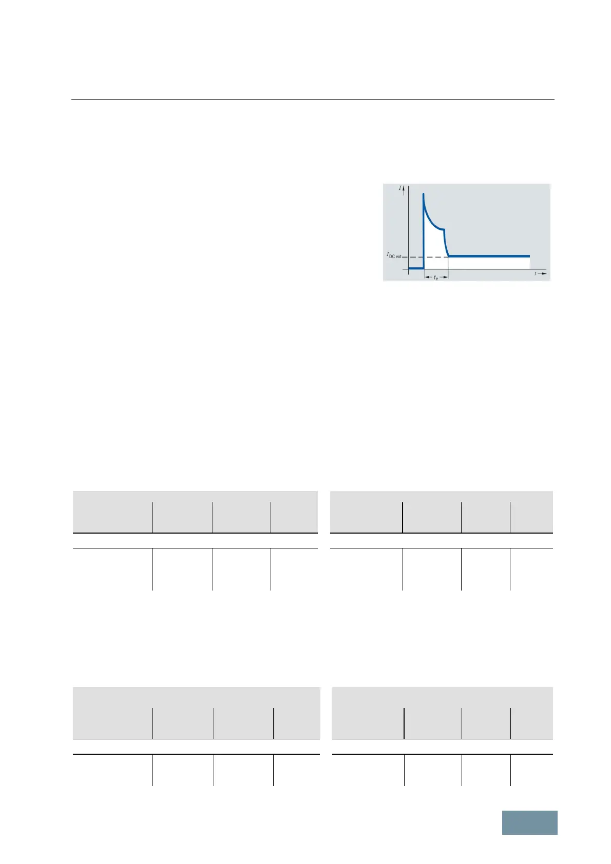
When selecting the external 24 V supply, it must be noted that the
capacitors in the electronics power supplies of all connected Cabinet
Modules must be charged when the power supply is switched on. The
24 V supply must therefore initially supply a peak current to charge these
capacitors. This peak current might correspond to a multiple of the
current I
DC ext
which is calculated from the sum of the values for all
connected Cabinet Modules as given in the tables on the following
pages. Account must also be taken of this peak current when protective
devices such as miniature circuit breakers are installed. The peak current
flows for a period t
e
lasting only a few 100 ms. The peak value is
determined by the impedance of the external 24 V supply or its
electronically limited maximum current.
Typical current waveform when the
external 24 V supply is switched on
The Line Connection Modules of Basic Line Connection Modules and Active Line Connection Modules provide
means of supplying auxiliary power (230 V 1AC and 24 V DC). The auxiliary voltages are either fed in to the Line
Connection Module from an external source via terminal -X100, or generated in the Line Connection Module itself by
option K76 "Auxiliary voltage generation (in the Line Connection Module)". In large-scale installations with high
auxiliary power requirements, it may be useful to install an Auxiliary Power Supply Module (available soon).
The following tables specify the basic requirements of the relevant S120 Cabinet Modules without taking into account
any options (e.g. Control Units or interface modules such as the TM31 or SMC30).
Basic Line Connection Modules (Line Connection Module + Basic Line Module)
The following components require an auxiliary voltage supply:
● 230 V 1AC: Main contactor / circuit breaker and cabinet ventilation
● 24 V DC: Open-loop / closed-loop control
Basic Line Connection Modules Basic Line Connection Modules
Frame size P
rated
[kW]
230 V 1AC
[A]
[A]
Frame size P
rated
at 690 V
[kW]
230 V 1AC
[A]
[A]
Line supply voltage 380 V to 480 V 3AC Line supply voltage 500 V to 690 V 3AC
HL+FBL 360 1.2 0.8 GL+FBL 355 1.2 0.8
JL+FBL 600 1.2 0.8 HL+FBL 630 1.2 0.8
JL+GBL 830 1.2 0.8 JL+GBL 1100 1.2 0.8
JL+GBL 1370 1.2 0.8
Active Line Connection Modules (Line Connection Module + Active Interface Module + Active Line Module)
The following components require an auxiliary voltage supply:
● 230 V 1AC: Precharging contactor and main contactor / circuit breaker
and cabinet ventilation
● 24 V DC: Open-loop / closed-loop control
Active Line Connection Modules
Active Line Connection
Modules
Frame size P
rated
[kW]
230 V 1AC
[A]
[A]
Frame size P
rated
at 690 V
[kW]
230 V 1AC
[A]
[A]
Line supply voltage 380 V to 480 V 3AC Line supply voltage 500 V to 690 V 3AC
JL+JIL+JXL 630 1.2 1.7 JL+JIL+JXL 1000 1.2 1.7
JL+JIL+JXL 900 1.2 1.7 JL+JIL+JXL 1400 1.2 1.7
JL+JIL+JXL 1700 1.2 1.7

 Loading...


