SINAMICS G150
Engineering Information
SINAMICS Engineering Manual – November 2015
Ó Siemens AG
331/528
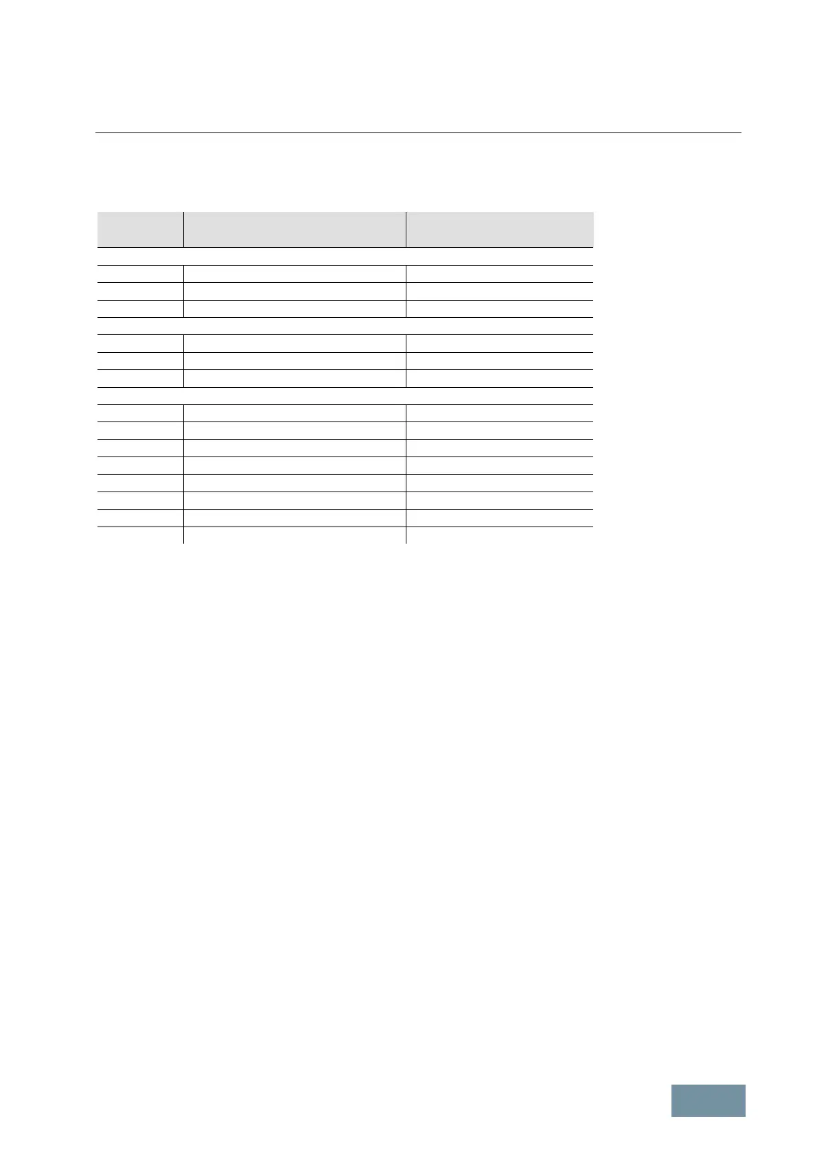
The table below specifies the minimum required motor cable lengths for SINAMICS G150 parallel converters,
whereby the given length is the distance between the converter output and the motor terminal box along the motor
cable.
Output power
[kW]
SINAMICS G150 converter cabinet unit
[Order No.]
Minimum motor cable length
1)
[m]
380 V to 480 V 3AC
630 6SL3710–2GE41–1AA3 13
710 6SL3710–2GE41–4AA3 10
900 6SL3710–2GE41–6AA3 9
500 V to 600 V 3AC
630 6SL3710–2GF38–6AA3 18
710 6SL3710–2GF41–1AA3 15
1000 6SL3710–2GF41–4AA3 13
660 V to 690 V 3AC
630 6SL3710–2GH41–1AA3 20
1350 6SL3710–2GH41–4AA3 18
1500 6SL3710–2GH41–5AA3 15
1750 6SL3710–2GH41–8EA3 12
1950 6SL3710–2GH42–0EA3 10
2150 6SL3710–2GH42–2EA3 8
2400 6SL3710–2GH42–4EA3 8
2700 6SL3710–2GH42–7EA3 8
1)
permissible tolerance: –20 %
Minimum required motor cable lengths for SINAMICS G150 parallel converters
The motor-side inverters can utilize both space vector modulation and pulse-edge modulation. Pulse-edge
modulation makes it possible to achieve a maximum output voltage which is almost equal to the value of the input
voltage (97 %). (For further details, please refer to chapter "Fundamental Principles and System Description",
sections "Maximum attainable output voltage with space vector modulation SVM" and "Maximum attainable output
voltage with pulse-edge modulation PEM".)
Despite of the current-balancing measures described above, it is not possible to obtain an absolutely symmetrical
current sharing which means that the currents of the rectifier sections or inverter sections in a SINAMICS G150
parallel converter are 7.5 % lower than the currents of the individual rectifiers or inverters. Allowance is already made
for this reduction factor in the current values in Catalog D 11 and in the table shown on the previous pages in this
manual.
Parameter p7003 must be set to "0" during commissioning (single winding system).
5.9.4 Special features to note when precharging SINAMICS G150 parallel converters
SINAMICS G150 parallel converters with power outputs of ≤ 1500 kW
At these G150 parallel converters, each of the two partial converters has a main rectifier equipped with thyristors and
a small precharging rectifier equipped with diodes, which is connected in parallel to the main rectifier. If both partial
converters are connected to the supply voltage at the same time, the DC links are charged via the two precharging
rectifiers and the associated precharging resistors. During this time, the main rectifiers are disabled (i.e. the thyristors
are not controlled). As soon as the DC links are charged, the main rectifier thyristors begin to be controlled in such a
way that they are triggered at the earliest possible moment. As a result, the thyristor rectifier essentially behaves
during operation in the same way as a diode rectifier. The operational current flows almost entirely via the main
rectifier since it encounters much less resistance than the parallel-connected precharging rectifier and its precharging
resistors.

 Loading...


