SINAMICS S120 Cabinet Modules
Engineering Information
SINAMICS Engineering Manual – November 2015
Ó Siemens AG
412/528
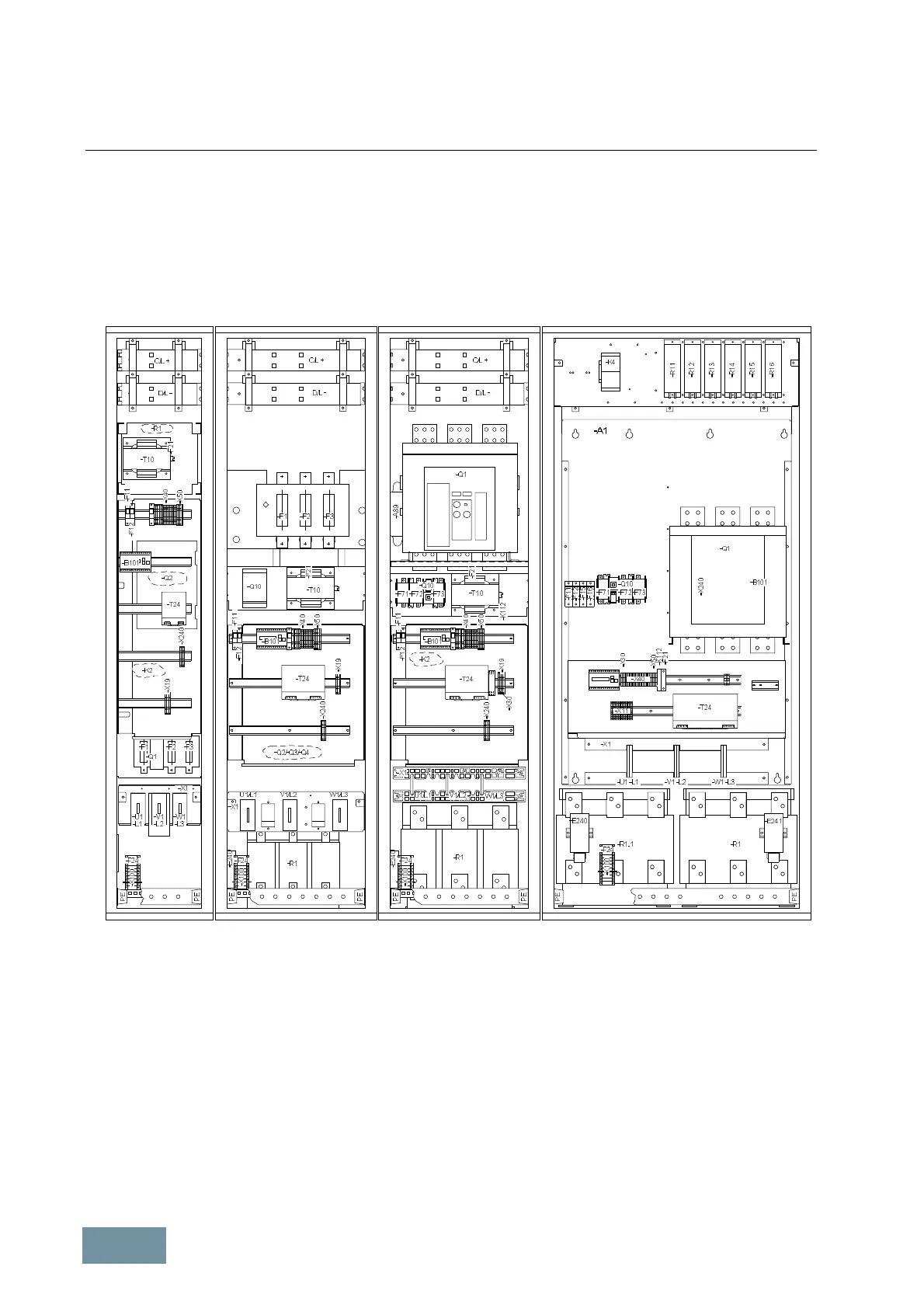
7.2.4 Line Connection Modules
7.2.4.1 Design
Line Connection Modules provide the line-side components as main circuit breaker and fuse-switch disconnector or
circuit breaker and provide the connection between the plants power supply and the Line Modules.
Various frame sizes are available depending on the input power rating.
Example configuration of air-cooled Line Connection Modules in frame sizes FL, GL/HL, JL, KL/LL
Different frame sizes have been developed to meet the requirements of different applications which vary in terms of
their power demand and optional components.
Fuse switch disconnectors are used as main switch on frame sizes FL, GL and HL. Circuit breakers of type 3WL are
installed on larger Line Connection Modules in frame sizes JL, KL and LL. The supply is brought in from below on all
units. A supply can also be brought in from the top, but this solution requires an additional cabinet.
Line Connection Modules are designed such that they do not need a cabinet fan for operation at standard ambient
conditions. Partitions and air-flow guides inside the cabinets obviate the need for fan cooling.
When combined with a Basic Line Module in combination with degree of protection IP23, IP43 or IP54, frame sizes
JL, KL and LL are equipped with a fan to provide extra internal cooling. On these models, the fan is mounted in the
hood, protected by fuses and connected separately to a terminal block in the terminal area.

 Loading...


