General Engineering Information for SINAMICS
Engineering Information
SINAMICS Engineering Manual – November 2015
Ó Siemens AG
267/528
3.6.4 Required ventilation clearances
Air-cooled SINAMICS units in Chassis format are forced ventilated by integrated fans in order to ensure an adequate
flow of cooling air through the power units.
When units in Chassis format are mounted in cabinets or other enclosures, it is important to provide openings of
sufficient size for the air inlet and the air outlet, as described in detail in the previous section.
In addition, sufficient clearances for the effective guidance of air must be provided inside the cabinet or enclosure so
that the cold incoming air can reach the Chassis unit unhindered and the heated exit air can flow away from it.
To ensure optimum cooling of air-cooled units in Chassis format, all components of these devices which produce
particularly high power losses and correspondingly high increases in temperature (power components of rectifiers
and inverters) are mounted on heat sinks through which cooling air flows. This cooling air flow is created by the fans
integrated in the Chassis unit. It passes through the components in a vertical direction from bottom to top, heating up
as it moves and cooling the components at the same time. The design of the power units as described and the
arrangement of the fans means that the cooling air is always sucked in from below and blown out at the top after
heating up inside the Chassis. For this reason, it is essential to ensure that sufficient cold cooling air can enter the
Chassis from below and that an adequate flow of heated air can exit the Chassis at the top.
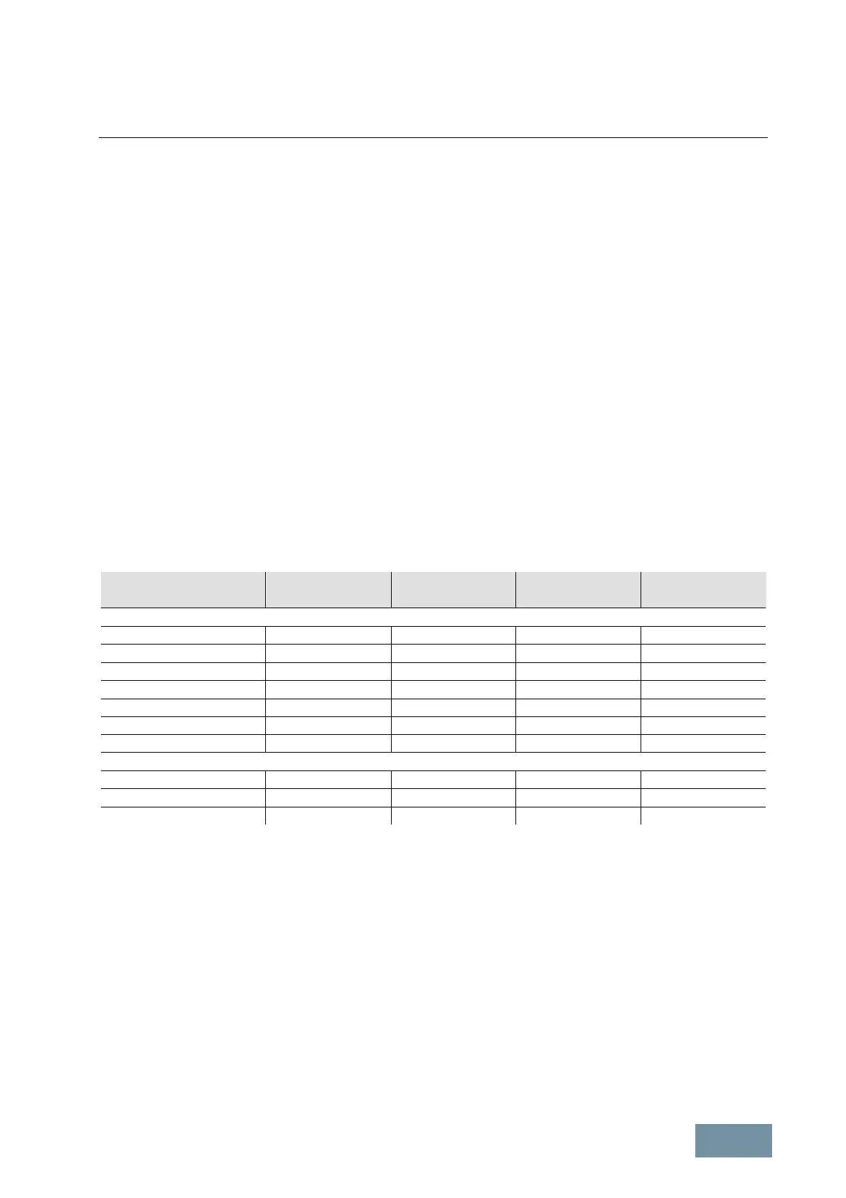
To provide proper cooling of Chassis units mounted in cabinets, it is therefore important to leave clearances for
guidance of cooling air in front of, underneath and on top of the Chassis. These clearances are specified in the table
below for the different Chassis variants. The values listed must be regarded as essential minimum values. The
clearances always refer to the outer edges of the Chassis units.
Drive component Frame size
Clearance front
1)
[mm]
Clearance top
[mm]
Clearance bottom
[mm]
S120 Chassis
Basic Line Modules FB, GB 40 250 150
Smart Line Modules GX, HX, JX 40 250 150
Active Interface Modules FI 40 250 150
Active Interface Modules GI 50 250 150
Active Interface Modules HI, JI 40 250 0
Active Line Modules FX, GX, HX, JX 40 250 150
Motor Modules FX, GX, HX, JX 40 250 150
G130
Power Modules FX 40 250 150
Power Modules GX 50 250 150
Power Modules HX, JX 40 250 150
1)
The clearances are valid for the area of cooling openings in the front cover.
Mandatory clearances required to ensure proper cooling of Chassis units
Nothing which might significantly hinder the cooling air flow to or from the Chassis may be positioned inside the
clearance area.
It is particularly important to ensure that electrical cables or busbars are not positioned in such a way that they
directly obstruct the air inlet or outlet openings on the Chassis or constrict the cross-section for cooling air flow in any
significant way.
Protective covers inside the cabinet must not obstruct the flow of cooling air to or from the Chassis. If necessary,
suitably constructed ventilation openings must be made in the protective covers.
More detailed information can be found in the relevant equipment manuals.
The diagrams below provide a graphic illustration of the information in the table above.

 Loading...


