SINAMICS G130
Engineering Information
SINAMICS Engineering Manual – November 2015
Ó Siemens AG
287/528
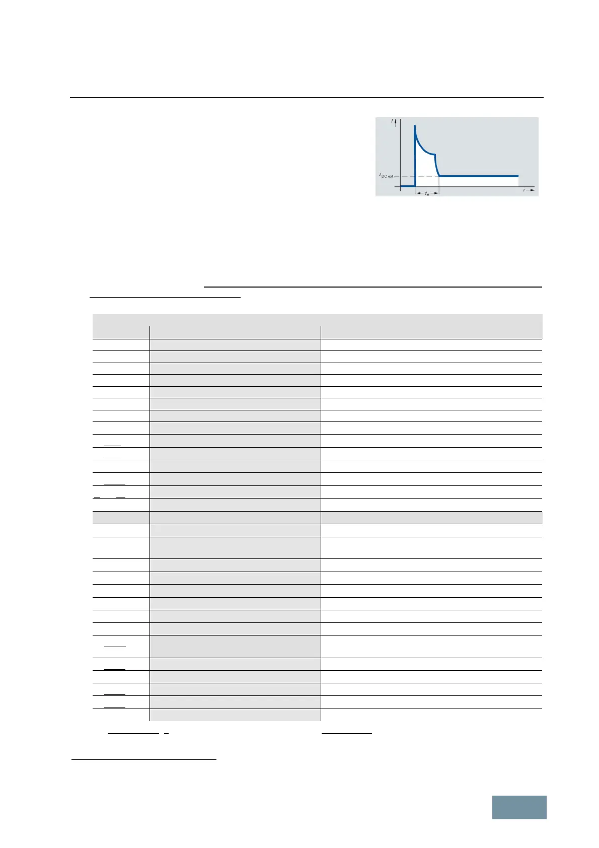
When an external 24 V supply is connected to terminal X9, it must be
noted that the capacitors in the electronics power supply of the
connected Power Module must be charged when the external 24 V
supply is switched on. In other words, the 24 V supply must initially
supply a peak curren t which can amount to a multiple of the current
I
DC ext
calculated according to the table, in order to charge these
capacitors. Account must be taken of this peak current when protective
devices such as miniature circuit breakers are installed. The peak current
flows for a period t
e
lasting only a few 100 ms. The peak value is
determined by the impedance of the external 24 V supply or its
electronically limited maximum current.
Typical current waveform when the
external 24 V supply is switched on
4.5 Factory settings (defaults) of customer interface on SINAMICS G130
The following factory settings are provided to simplify configuring of the customer interface and commissioning. The
interfaces can also be assigned as required at any time.
1. The converter is controlled via the PROFIBUS interface (CU320-2 DP) or the PROFINET interface (CU320-2
PN) which are integrated as standard. The digital inputs and outputs on the Control Unit are used to incorporate
external alarm and/or error messages and control signals.
Terminal block on the CU320-2 Control Unit
-X122 Factory setting Comment
DI0 Not assigned
DI1 Not assigned
DI2 Not assigned
DI3 Acknowledge fault
DI16 Not assigned
DI17 Not assigned
M1
M (GND)
DI/DO8 Inverter enable (Run)
DI/DO9 No fault
M (GND)
DI/DO10 P24 Factory-set as output
DI/DO11 External alarm
1)
Low active
M (GND)
-X132
DI4 OFF 2
1)
DI5 OFF 3
1)
Ramp-down along quick-stop ramp, only of relevance in
conjunction with the Braking Module
DI6 External fault
1)
DI7 Not assigned
DI20 Not assigned
DI21 Not assigned
M2
M (GND)
DI/DO12 Error message acknowledgement, Braking
Module
Output is used (factory-set) in conjunction with the Braking
Module
DI/DO13 P24 Factory-set as output
M (GND)
DI/DO14 P24 Factory-set as output
DI/DO15 P24 Factory-set as output
M (GND)
The factory settings of the bidirectional inputs/outputs are underscored.
1)
A jumper must be inserted here if these inputs are not used.

 Loading...


