Fundamental Principles and System Description
Engineering Information
SINAMICS Engineering Manual – November 2015
Ó Siemens AG
212/528
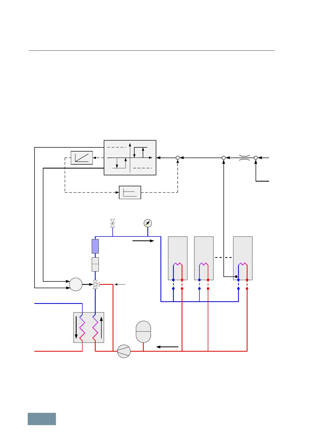
When the control deviation x exceeds the upper switching hysteresis x
u
, the actuating motor is switched on and
operates in the forward direction; when the control deviation falls below the lower switching hysteresis x
l
, the
actuating motor is switched off again. If the control deviation falls below the switching hysteresis -x
u
in the negative
direction, the actuating motor operates in the reverse direction until the control deviation has been eliminated and the
actuating motor is switched off again when switching hysteresis -x
l
is reached.
From the control point of view, the actuating motor on the 3-way valve behaves as an I-controller. It is advisable to
utilize the feedback shown by the dashed line in order to obtain a stable behavior as a P-controller.
The 3-way valve is controlled such that the bypass (path B-AB) is opened when the coolant is cold. The coolant
bypasses the heat exchanger and the temperature of the heat sink and the coolant rises as a result of heat losses
from the power semiconductors in the SINAMICS units. When the temperature T
act
at the coolant inlet of the
SINAMICS units reaches the specified setpoint T
set
, the 3-step controller closes the bypass and opens the path
through the heat exchanger (path A-AB).
Basic
Line
Module
Motor
Module
1
Motor
Module
n
Pressure-relief
valve < 6 bar
Pressure
indicator
Closed
pressurizer
Pump
Inspection
glass
Dirt trap
Heat
exchanger
Inflow
Return flow
Hose
connection
3-way valve
(bypass valve)
for temperature
control
Liquid-cooled SINAMICS
S120 units in Chassis format
M
AB
B
A
Actuating motor
for 3-way valve
Close bypass
Open bypass
x
l
x
u
-x
l
-x
u
y
x
Emulation of
the actuating
motor
P-feedback
T
set
T
act
ΔT
L
T
a
T
max
T
min
x
_
+
(Parameter
r0037[19])
+y1
-y1
3-step controller
Example of coolant temperature control by means of a 3-way valve in order to prevent condensation
Coolant temperature control as a function of ambient temperature and air humidity
The table in section "Protection against condensation" is the basis for calculating the required temperature difference
ΔT
L
that must be added to the ambient temperature T
a
so as to ensure that the setpoint T
set
for the coolant
temperature always remains higher than the dew point of the ambient air. This table states the dew point T
dp
as a
function of ambient temperature T
a
and relative air humidity Φ.

 Loading...


