SINAMICS G150
Engineering Information
SINAMICS Engineering Manual – November 2015
Ó Siemens AG
316/528
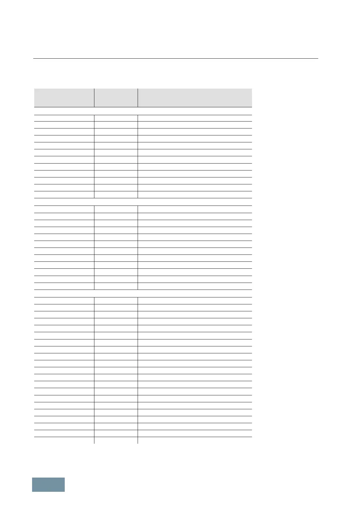
The precharging currents decay in accordance with an e-function until the precharging process is completed after a
period of typically 1 to 2 s. Due to the temperature rise in the precharging resistors during the process, the minimum
permissible interval for complete precharging of the DC link is 3 minutes.
Rated power
of G150
at 400 V / 500 V / 690 V
Rated
output current
Line current (initial rms value) at the
beginning of DC link precharging
at 400 V / 500 V / 690 V
380 V – 480 V 3AC
110 kW 210 A 5 A
132 kW 260 A 6 A
160 kW 310 A 6 A
200 kW 380 A 8 A
250 kW 490 A 13 A
315 kW 605 A 13 A
400 kW 745 A 13 A
450 kW 840 A 13 A
560 kW 985 A 17 A
630 kW
1)
1120 A 13 A
1)
710 kW
1)
1380 A 13 A
1)
900 kW
1)
1560 A 13 A
1)
500 V – 600 V 3AC
110 kW 175 A 4 A
132 kW 215 A 5 A
160 kW 260 A 5 A
200 kW 330 A 8 A
250 kW 410 A 10 A
315 kW 465 A 10 A
400 kW 575 A 13 A
500 kW 735 A 15 A
560 kW 810 A 15 A
630 kW
1)
860 A 10 A
1)
710 kW
1)
1070 A 13 A
1)
1000 kW
1)
1360 A 15 A
1)
660 V – 690 V 3AC
75 kW 85 A 4 A
90 kW 100 A 4 A
110 kW 120 A 4 A
132 kW 150 A 4 A
160 kW 175 A 5 A
200 kW 215 A 7 A
250 kW 260 A 7 A
315 kW 330 A 11 A
400 kW 410 A 15 A
450 kW 465 A 15 A
560 kW 575 A 17 A
710 kW 735 A 21 A
800 kW 810 A 21 A
1000 kW
1)
1070 A 17 A
1)
1350 kW
1)
1360 A 21 A
1)
1500 kW
1)
1500 A 21 A
1)
1750 kW
1)
1729 A 142 A
1)
1950 kW
1)
1948 A 142 A
1)
2150 kW
1)
2158 A 165 A
1)
2400 kW
1)
2413 A 172 A
1)
2700 kW
1)
2752 A 172 A
1)
1)
G150 parallel connection / the specified precharging currents represent the partial precharging current of one of the two rectifier sections
SINAMICS G150 cabinet units: Line currents at beginning of precharging (initial rms values)

 Loading...


