Installing the Control System
2-10
SINUMERIK 802C base line
Start-Up
Drives with analog interface
Signals:
A voltage and an enable signal are output.
z
AOn (SETPOINT)
Analog voltage signal in the range ± 10 V to output a speed setpoint
z
AGNDn (REFERENCE SIGNAL)
Reference potential (analog ground) for the setpoint signal, internally
connected to logic ground.
z
SEn (SERVO ENABLE)
Relay contact pair controlling the enable of the power section, e.g. of a
SIMODRIVE drive unit controlled via a PLC program.
Signal parameters
The setpoint is output as an analog differential signal.
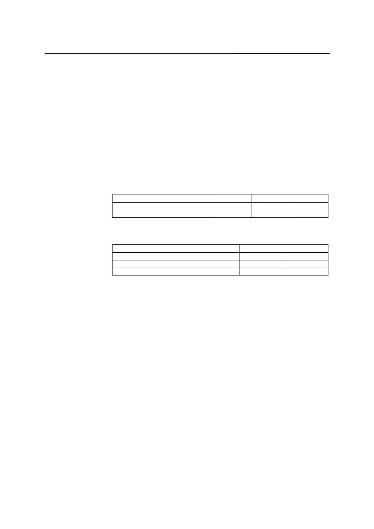
Table 2–3 Electrical parameters of the signal outputs for step-switching drives
Parameter Min Max Unit
Voltage range –10.5 10.5 V
Output current –3 3 mA
Relay contact
Table 2–4 Electrical parameters of the relay contacts
Parameter Max. Unit
Switching voltage 50 V
Switching current 1 A
Switching power 30 VA
Cable length: max. 35 m