Start-Up
4-6
SINUMERIK 802C base line
Start-Up
4.2 Turning on and booting the control system
Procedure
z
Inspect the system visually for:
proper mechanical installation with tight electrical connections
supply voltages
connections for shielding and grounding.
z
Turn on the control system.
Notice
Providing memory and start–up switch S3 are set correctly (see Fig.2–6), the
control system boots.
Start–up switch S3 (hardware)
The CNC is provided with a start–up switch to assist start–up of the control
system.
This switch can be actuated using a screw driver.
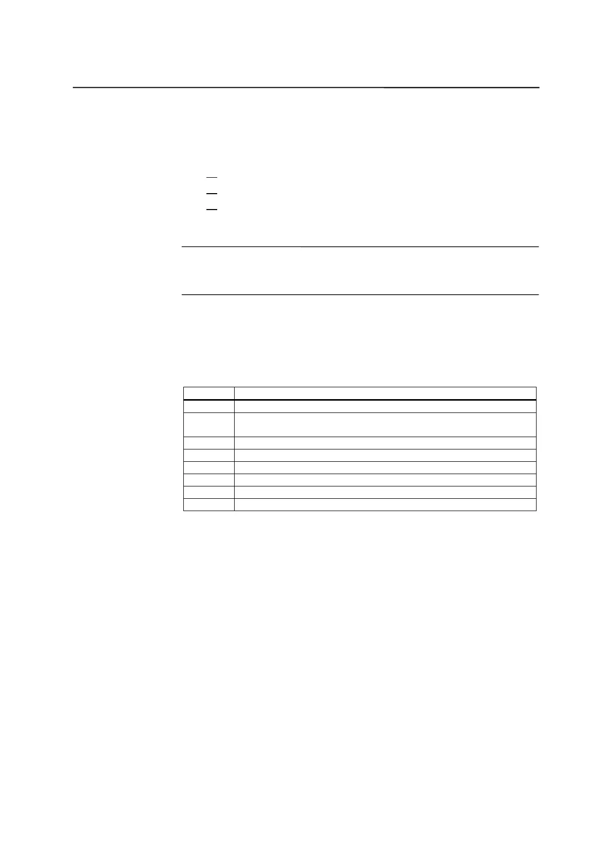
Table 4–2 Start–up switch settings
Position Meaning
0 Normal power-up
1 Power-up with default machine data (user data determined by the
software version)
2 System software update
3 Power-up with saved data
4PLC stop
5 Reserve
6 Assigned
7 Assigned
The switch position comes into effect with next power-up and is displayed on
the screen when the control system powers up.
Start–up switch
(software)
In addition to the hardware start–up switch, the following functions can also be
carried out in the Diagnosis/Start–up/Start–up switch menu:
z
Normal boot (Start–up switch position 0)
z
Boot with default machine data (Start–up switch position 1)
z
Boot with saved data (Start–up switch position 3)
These power-up functions have a higher priority than the hardware start-up
switch.
Booting the control system
When the control system is turned on for the first time, an initial state of the
control system is established automatically. All memory areas are initialized
and are loaded with previously stored default data.
The PLC area of retentive bit memories is explicitly erased.