To prevent stopping in continuous-path mode, M17 must not be programmed alone in a
block.
Example of a subroutine: G64 F2000 G91 Y10 X10
X10 Z10 M17
Bit 1 = 0:
M01:
conditional program stop is always output to PLC, irrespective of whether the M01
signal is active or not.
Fast auxiliary function output M=QU(1) is inactive because M01 is assigned to the 1st
M function group and thus is always output at block end.
Bit 1 = 1:
M01:
conditional program stop is only output to PLC, if M01 is also active.
This thus enables optimal run-time processing of the part program.
With fast auxiliary function output M=QU(1), M1 is output during the movement; thus it
is
possible to
traverse blocks in continuous-path mode with programmed M01 as long as
M01 is not active.
The request of the M01 signal with M=QU(1) no longer occurs at block end but during
the movement.
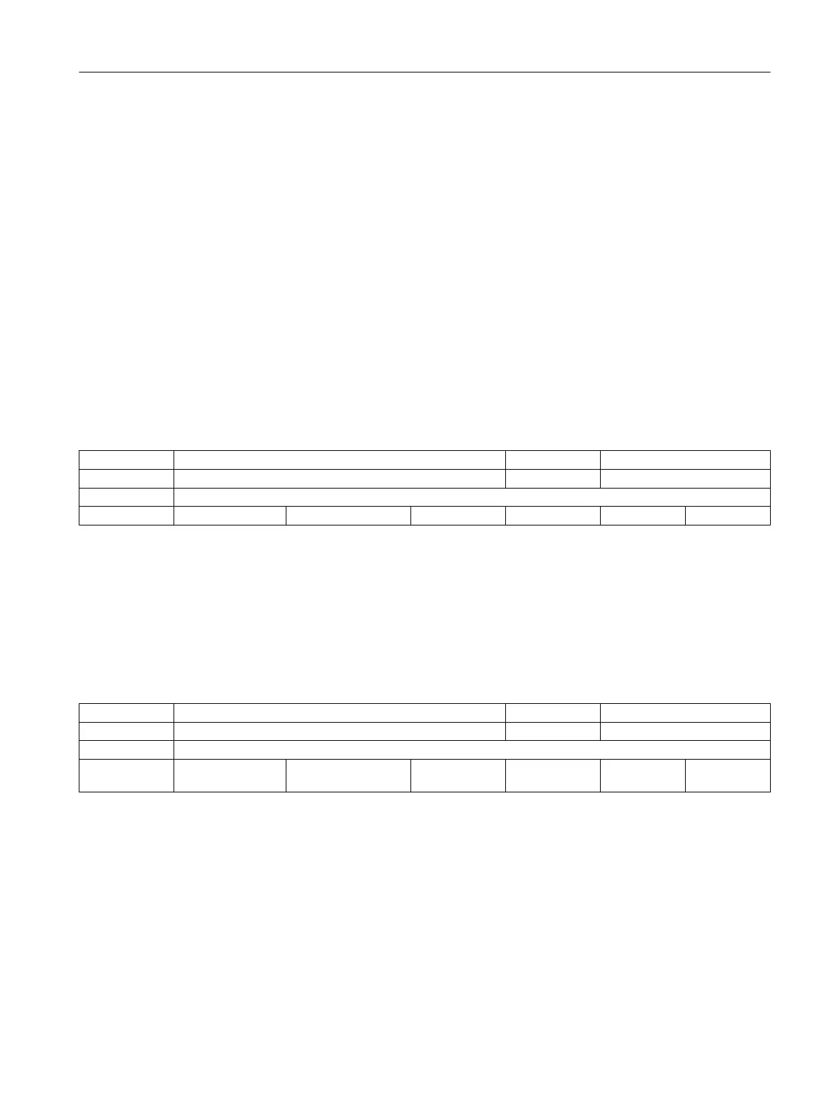
20850 SPOS_TO_VDI C04, C03 S1
- Output of M19 to PLC on SPOS/SPOSA BYTE PowerOn
-
- - 0, 0, 0, 0, 0, 0, 0, 0... - - 1/1 M
Description: Bit 0 = 0:
When bit 19 is also set to '0' in MD35035 $MA_SPIND_FUNCTION_MASK, auxiliary function
M19 is not generated with SPOS and SPOSA. This also eliminates the acknowledgement
time for the auxiliary function, which can cause faults wiith very short blocks.
Bit 0 = 1:
When SPOS and SPOSA are programmed in the part program, auxiliary function M19 is
generated and output to the PLC. The address extension corresponds to the spindle
number.
Related to:
SPIND_FUNCTION_MASK
21000 CIRCLE_ERROR_CONST C06 -
mm Circle end point monitoring constant DOUBLE NEW CONF
-
- - 0.01, 0.01, 0.01, 0.01,
0.01, 0.01, 0.01, 0.01...
0.0 - 2/2 M
Description: This machine data is used to specify the permissible absolute circle error [mm].
When a circle is programmed, both conditions (that the distances from the programmed
center
point to
the start and end points (circle radius) must be the same and that the
center point of the circle must be located on the perpendicular bisector of the
straight line connecting the start and end points (perpendicular bisector of the
circular plane)) apply.
The fact that the circular parameters can be freely programmed means that these
conditions are not usually met exactly in the case of circular-path programming with
I, J, and K (the circle is "overdefined").
The maximum permissible difference between the two radii that is accepted without an
alarm,
as well
as the distance between the programmied center point of the circle and
the perpendicular bisector described above, is defined by the larger value in the
following data:
Machine data
3.3 Channel-specific machine data
Parameter Manual
Parameter Manual, 08/2015, 6FC5397-8EP40-0BA1 161
 Loading...


