Parameter Manual
Operating Instructions, 08/2013, 6FC5397-8EP40-0BA0
333
Detailed descriptions of interface signals
4.3 Signals from / to HMI
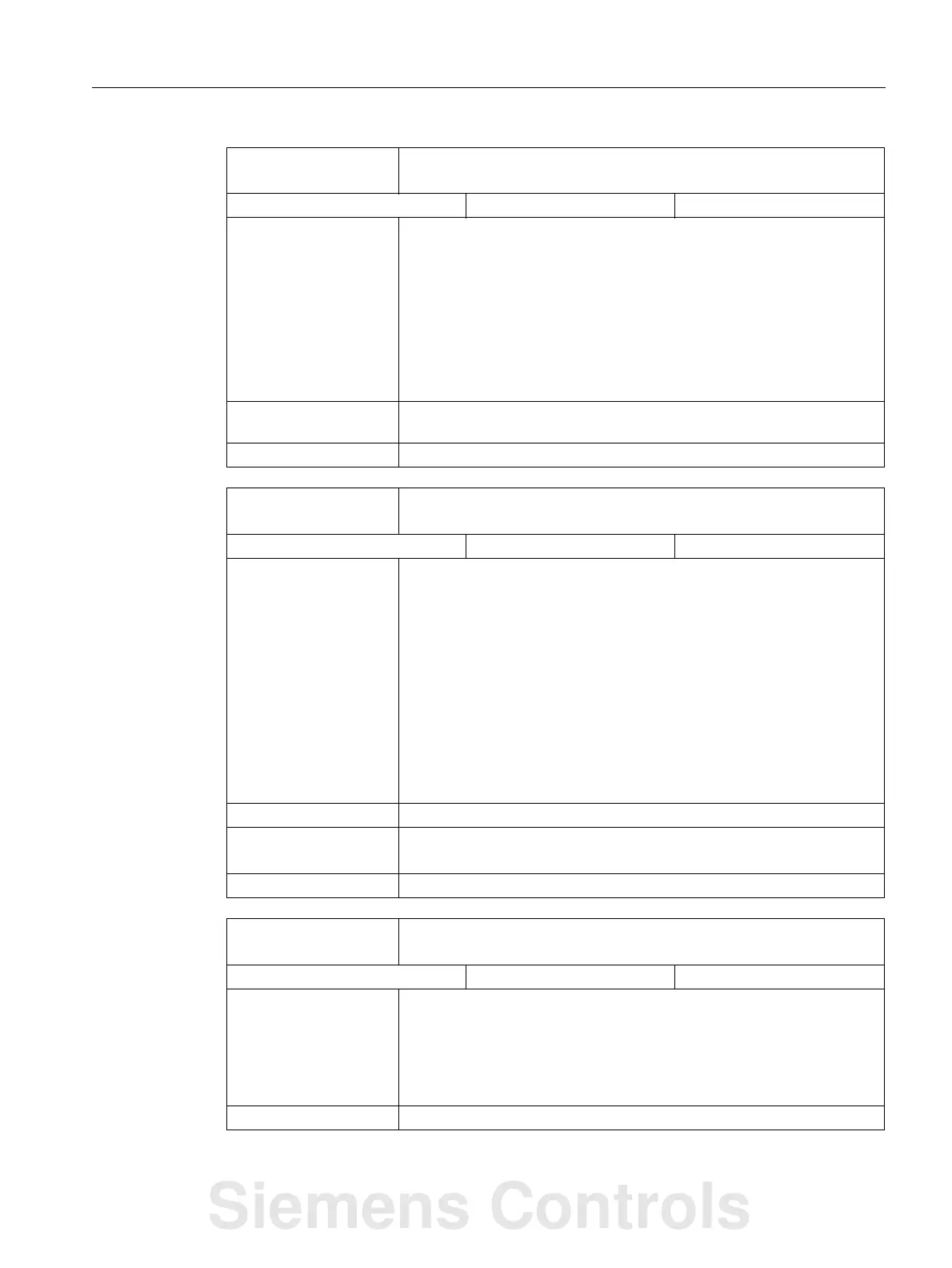
DB1700
DBX7.1
NC start
Signal(s) to PLC (HMI → PLC)
Edge evaluation: Yes Signal(s) updated: Cyclic
Signal state 1 or edge
change 0 → 1
AUTOMATIC mode:
The selected NC program is started or continued, or the auxiliary functions
that were saved during the program interruption are output.
If data is transferred from the PLC to the NC during program status
"Program interrupted," then this data is immediately processed with NC
start.
MDI mode:
The entered block information or part program blocks are released for
execution.
Signal state 0 or edge
change 1 → 0
No effect.
Note for the reader Function Manual Basic Functions K1
DB1700
DBX7.3
NC stop
Signal(s) to PLC (HMI → PLC)
Edge evaluation: No Signal(s) updated: Cyclic
Signal state 1 AUTOMATIC or MDI mode:
Execution of the active part program in the channel is stopped. The axes
(not spindles) are braked to a standstill maintaining the parameterized
acceleration rates.
• Program status: Stopped
• Channel status: Interrupted
JOG mode:
In the JOG mode, incompletely traversed incremental paths (INC...) are
executed at the next NC start.
Note:
If data is transferred to the NCK after NC stop (e.g. tool offset), then this
data is processed with the next NC start.
Signal state 0 No effect.
corresponding to ... DB3300 DBX3.2 (program status stopped)
DB3300 DBX3.6 (channel status interrupted)
Note for the reader Function Manual Basic Functions K1
DB1700
DBX7.7
Reset
Signal(s) to PLC (HMI → PLC)
Edge evaluation: No Signal(s) updated: Cyclic
Signal state 1 The channel is reset. The initial settings are made (e.g. for G functions).
The channel alarms are deleted if they are not POWER ON alarms. The
"Reset" signal must be issued by the PLC (e.g. using a logic operation with
the reset key on the MCP). The signal is only evaluated by the selected
channel.
The program status changes to "Interrupted".
Signal state 0 No effect.
Siemens Controls