Parameter Manual
Operating Instructions, 08/2013, 6FC5397-8EP40-0BA0
441
PLC User Interface
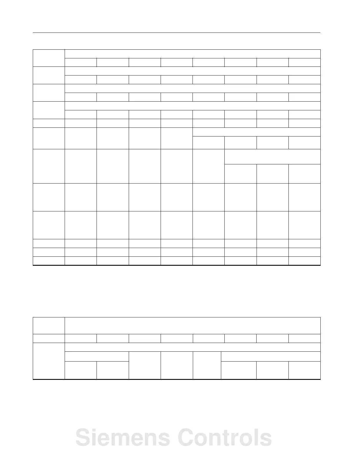
5.8 Channel signals
Controls signals to axes in Work
8 Activate machine-related protection zone
Area 8 Area 7 Area 6 Area 5 Area 4 Area 3 Area 2 Area 1
9 Activate machine-related protection zone
Area 10 Area 9
10 Activate channel-specific protection zone
Area 5 Area 5 Area 5 Area 5 Area 5 Area 5 Area 5 Area 5
11 Activate channel-specific protection zone
Area 10 Area 9
12
13 Do not
block tool
Deactivate
workpiece
counter
Activate fixed feedrate
Feed 4 Feed 3 Feed 2 Feed 1
14 No tool
change
commands
JOG circle Activate
associated
M01
Negative
direction for
simulation
contour
handwheel
Simulation
contour
handwheel
ON
Activate contour handwheel (bit/binary
coded)
Handwheel
1
Handwheel
2
15 Activate
skip block 9
Activate
skip block 8
Invert
contour
handwheel
direction
16 Program
branches
(GOTOS)
control
17
18
19
1)
Select single-block type selection using the softkey.
2)
31 positions (Gray code)
DB3200 Signals to NCK channel [r/w]
PLC -> NCK interface
Byte Bit 7 Bit 6 Bit 5 Bit 4 Bit 3 Bit 2 Bit 1 Bit 0
1000 Axis 1 in Work
Traversing keys Rapid
traverse
override
Traversing
key
distance
disable
Feedrate
stop
Activate handwheel (bit/binary coded)
1)
Plus Minus 2 1
1)
The handwheel number is represented according to the $MD_HANDWH_VDI_REPRESENTATION machine data in a bit-
coded (=0) or binary-coded (=1) manner.
2)
Machine function: the machine function is only entered if the "INC inputs in the operating-mode signal range active" signal
(DB2600DBX1.0) is not set.
Siemens Controls