● PPU 240.3 BASIC (vertical operator panel)
● PPU 241.3 BASIC (horizontal operator panel)
● PPU 260.3 (vertical operator panel)
● PPU 261.3 (horizontal operator panel)
● PPU 280.3 (vertical operator panel)
● PPU 281.3 (horizontal operator panel)
Quantity structure
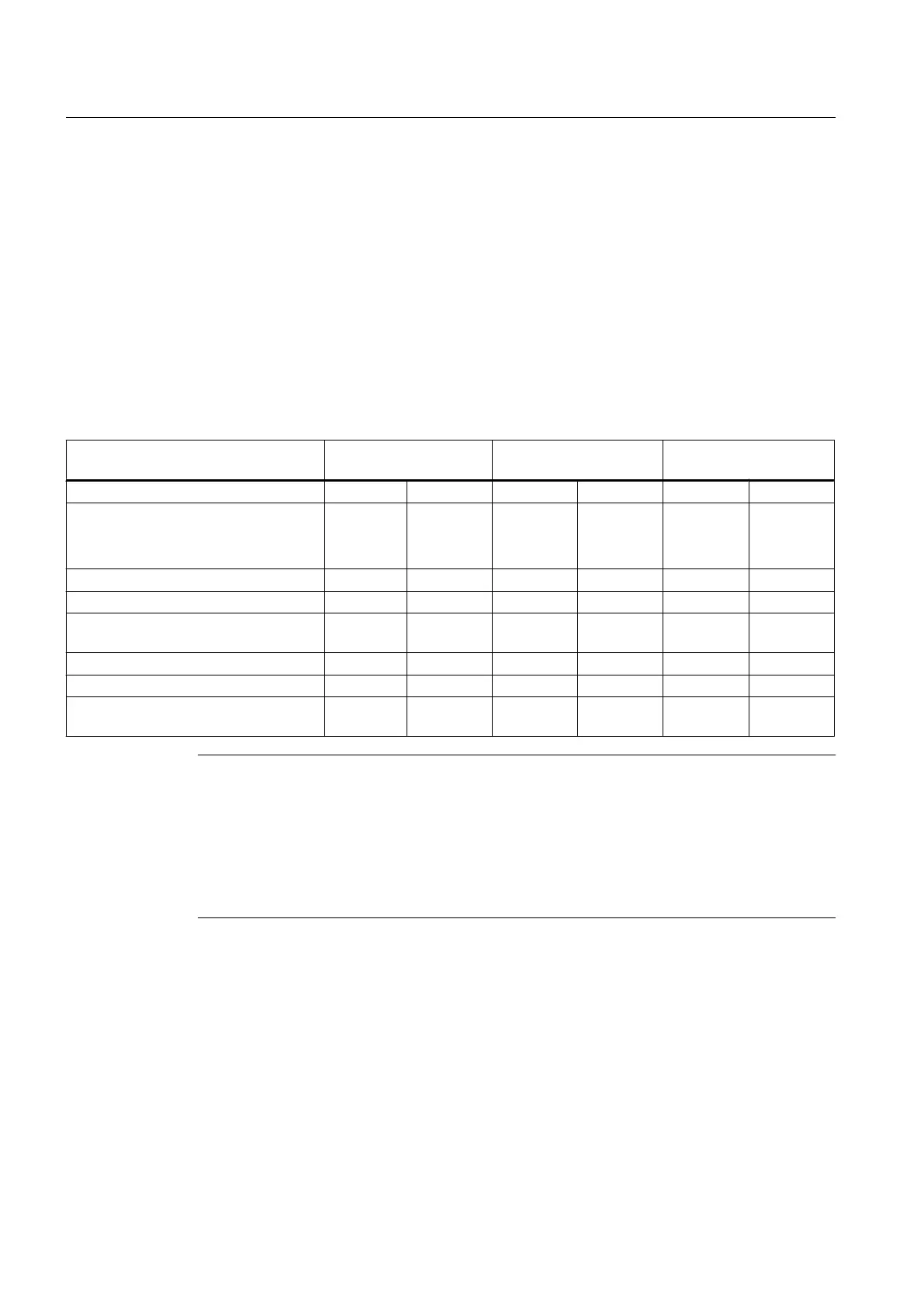
The following table shows the quantity structures for the different control versions:
Function PPU 240.3 / 241.3
BASIC
PPU 260.3 / 261.3 PPU 280.3 / 281.3
Turning Milling Turning Milling Turning Milling
Non-volatile memory (NVRAM):
● For OEM data
● For user data
512 KB
3 MB
512 KB
3 MB
512 KB
5 MB
512 KB
5 MB
512 kB
8 MB
512 kB
8 MB
Number of axes/spindles 3 4 3 4 3 4
Maximum number of axes/spindles 5 5 6 6 6 / 8 * 6
Maximum number of axes with drive-
based Safety Integrated
5 5 6 6 6 / 8 * 6
Axis expansion with NX10.3 -- -- -- 1 1 1
Number of DRIVE-CLiQ interfaces 3 3 3 3 3 3
Maximum number of I/O modules
(digital/analog)
3 3 4 4 5 5
Note
Axis extensions for PPU 28x.3
With the help of a NX10.3, the following extensions can be connected:
● The maximum number of axes can be increased to eight, six of which can be connected
to the PPU and two to the NX10.3.
● One high-speed spindle (e.g. 24,000 rpm with four pole pairs) can be connected to the
NX10.3 and five axes to the PPU.
System description
2.1 Controller features
PPU
14 Manual, 01/2014, 6FC5397-2DP40-3BA3

 Loading...


