7.2.1 Operator controls and display elements
Operator controls
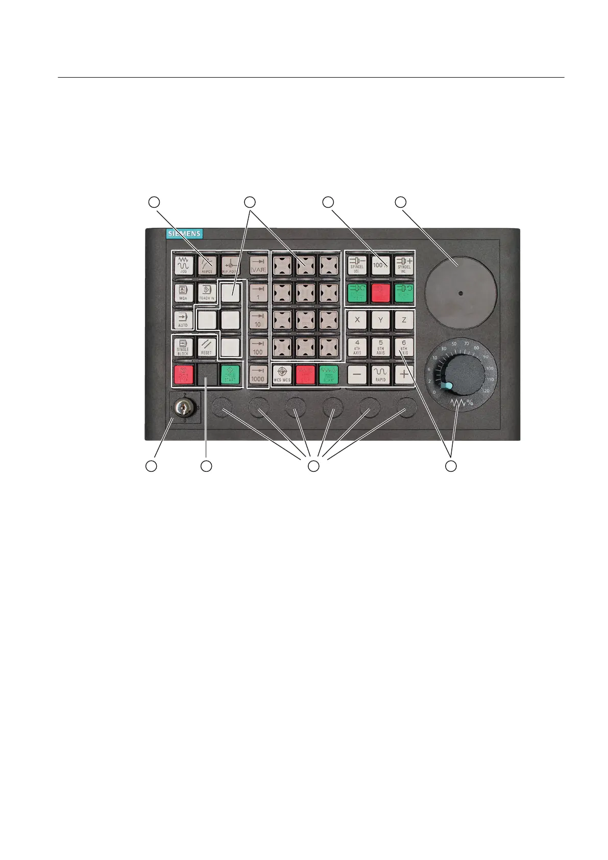
① Operating modes and machine functions
② 16 customer keys
③ Spindle control
④ Slot for EMERGENCY STOP button or override switch for the spindle control
⑤ Feed control with override switch
⑥ Slots for control devices 16 mm
⑦ Program control
⑧ Key-operated switch
Figure 7-12 Arrangement of the MCP 310C PN control elements
Emergency Stop button
If an EMERGENCY STOP button is to be retrofitted, refer to Chapter Operator controls and
display elements (Page 94) of the MCP 483C PN.
Connectable components
7.2 MCP 310C PN
PPU
Manual, 01/2014, 6FC5397-2DP40-3BA3 113

 Loading...


