8. Place the cover ② on the rotary knob and snap it into position.
9. Fold and fasten the connecting cable ⑦ as shown in the figure on the right.
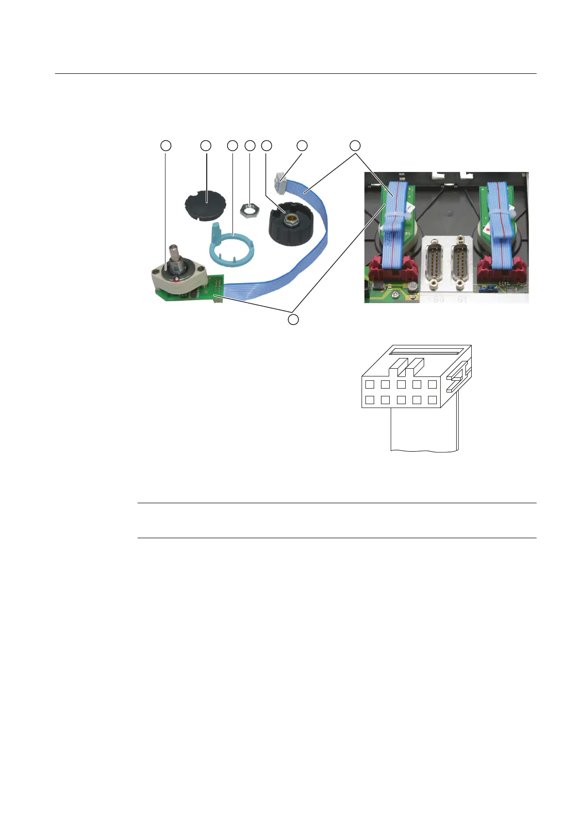
① O-ring Detail diagram of the connector
② Cap
③ Arrow ring
④ Fastening nut
⑤ Rotary knob
⑥ Connection plug
⑦ Connecting cable
⑧ Terminal board
Figure 7-11 Installation of rotary switch
Proceed in the same way to install the second rotary switch.
Note
It is essential to use the correct tightening torques.
7.2 MCP 310C PN
Description
The 310C PN machine control panel enables user-friendly operation of the machine functions.
It can be used in the SINUMERIK 828D system for machine-level operation of milling and
turning machines.
All keys are designed with replaceable caps for machine-specific adaptations. The key caps
can be freely inscribed using laser. Clear key caps can be used as an alternative.
Connectable components
7.2 MCP 310C PN
PPU
Manual, 01/2014, 6FC5397-2DP40-3BA3 111

 Loading...


