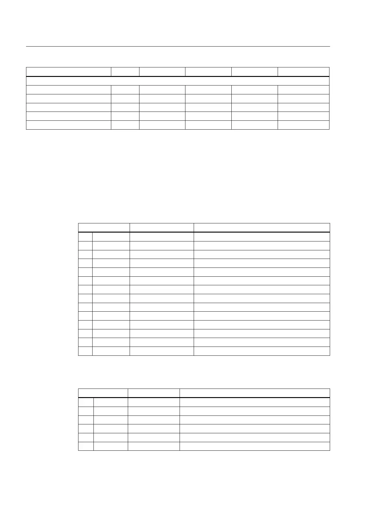
I/O module Bus Device name IP address Input addresses Output addresses
PN/PN coupler * PN pn-pn-coupler20 20 96 … 111 96 … 111
External machine control panel PN mcp-pn64 64 112 … 125 112 … 121
Reserved -- -- 126 … 131 122 ... 123
Sentron PAC 4200 * PN pac4200-pn21 21 132 ... 143 132 ... 143
Sentron PAC 3200 * PN pac3200-pn22 22 144 ... 155 144 ... 155
The Index n, m, d is always the start address of the address range.
*) The IP address of these components is not set using a switch but rather configured appropriately.
6.5 Digital inputs/outputs
Pin assignment for X122
Pin Signal name Meaning
1 DI0 DI0 Digital input 0
2 DI1 DI1 Digital input 1
3 DI2 DI2 Digital input 2
4 DI3 DI3 Digital input 3
5 DI16 DI16 Digital input 16
6 DI17 DI17 Digital input 17
7 M2 MEXT2 Ground for pins 1...6
8 P1 P24EXT1 +24 V power supply
9 IO8 DI/DO8 Digital input/output 8
10 IO9 DI/DO9 Digital input/output 9
11 M1 MEXT1 Ground for pins 9, 10, 12, 13
12 IO10 DI/DO10 Digital input/output 10
13 IO11 DI/DO11 Digital input/output 11
14 M1 MEXT1 Ground for pins 9, 10, 12, 13
X132 pin assignment
Pin Signal name Meaning
1 DI4 DI4 Digital input 4
2 DI5 DI5 Digital input 5
3 DI6 DI6 Digital input 6
4 DI7 DI7 Digital input 7
5 DI20 DI20 Digital input 20
6 DI21 DI21 Digital input 21
Interface description
6.5 Digital inputs/outputs
PPU
76 Manual, 01/2014, 6FC5397-2DP40-3BA3

 Loading...


