Pin Signal name Meaning
7 M2 MEXT2 Ground for pins 1...6
8 P1 P24EXT1 +24 V power supply
9 IO12 DI/DO12 Digital input/output 12
10 IO13 DI/DO13 Digital input/output 13
11 M1 MEXT1 Ground for pins 9, 10, 12, 13
12 IO14 DI/DO14 Digital input/output 14
13 IO15 DI/DO15 Digital input/output 15
14 M1 MEXT1 Ground for pins 9, 10, 12, 13
Connection notes
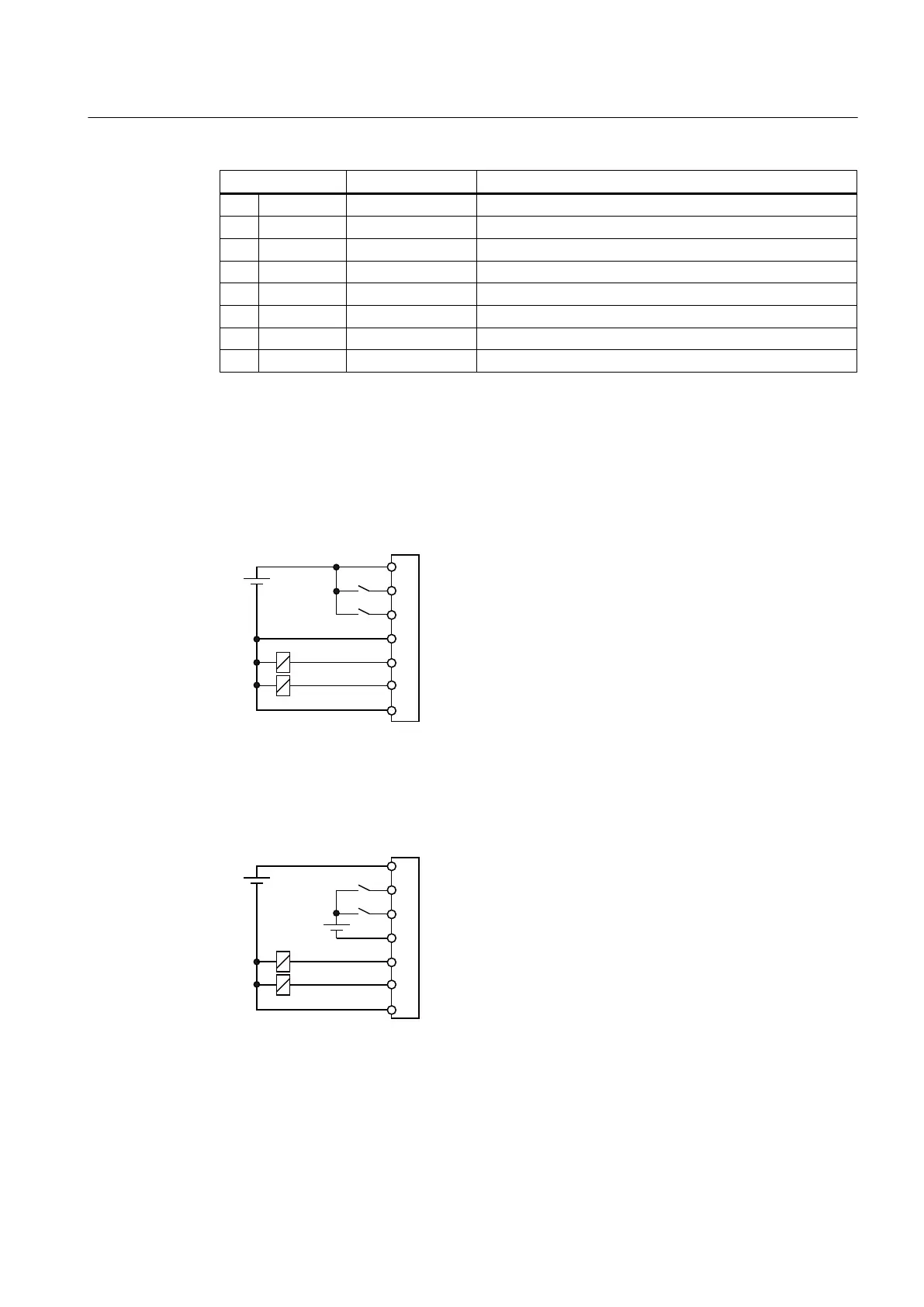
1. Recommended connection:
If both inputs and outputs are operated on a digital inputs/outputs group, it is recommended
that both the inputs and the outputs are fed with the same 24 VDC supply:
3
','2
','2
0
','2
','2
0
'&9
Figure 6-2 Inputs and outputs on the same supply
2. Not recommended connection:
If the inputs and outputs supplied separately with power, the input current can exceed the
permissible value of 15 mA according to EN61131-2. This may possibly cause the signal
source to be overloaded:
3
','2
','2
0
','2
','2
0
'&9
'&9
Figure 6-3 Inputs and outputs on different supplies
Interface description
6.5 Digital inputs/outputs
PPU
Manual, 01/2014, 6FC5397-2DP40-3BA3 77

 Loading...


