Note
If an additional encoder is connected to a Motor Module, it is assigned to this drive as encoder
2 in the automatic configuration. At a Double Motor Module, an encoder at X201 is assigned
to the 2nd feedrate as 2nd measuring system.
960
338
;
;
;
$FWLYH
/LQH
0RGXOH
;;;;
;;;;
;;;;
;
6LQJOH
0RWRU
0RGXOH
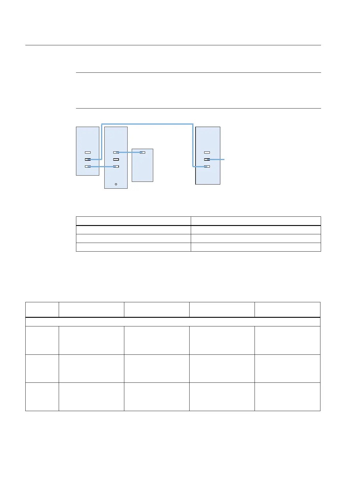
Figure 5-3 Example: Topology with VSM for booksize and chassis components
Component VSM connection
Active Line Module booksize X202
Active Line Module (chassis) X402
Power Modules The VSM is not supported.
5.3 Topology rules for Safety Integrated functions
Number
of axes
Port 1 at the PPU
X100
Port 2 at the PPU
X101
Port 3 at the PPU
X102
Example in the figure:
SINAMICS S120 booksize
5 1 x LM
4 x MoMo
1 x SMy at the 4th MoMo
1 x TM54F
1x MoMo
1 x Hub DMx
4 x SMy at the Hub DMx
not used ---
6 1 x LM
4 x MoMo
1 x SMy at the 4th MoMo
1 x TM54F
2x MoMo
1 x Hub DMx
5 x SMy at the Hub DMx
not used ---
7 1 x LM
4 x MoMo
1 x SMy at the 4th MoMo
1 x TM54F
2x MoMo
1 x Hub DMx
5 x SMy at the Hub DMx
1 x NX10.3
1 x TM54F
1 x MoMo
1 x SMy at the MoMo
---
Rules for permitted topologies
5.3 Topology rules for Safety Integrated functions
PPU
58 Manual, 01/2014, 6FC5397-2DP40-3BA3

 Loading...


