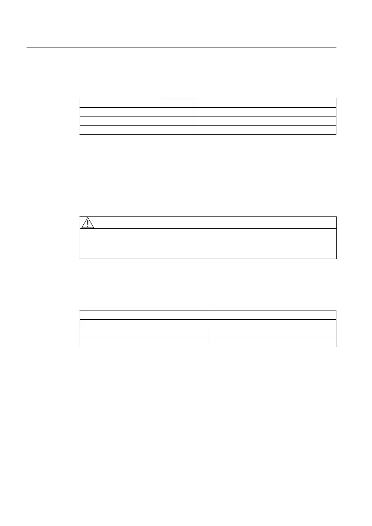
Pin assignment
Table 7-83 Pin assignment at X1 screw-type terminal block
Pin Signal name Signal type Meaning
1 P24 VI 24 VDC power supply
2 M GND Ground
3 PE GND Protective ground
Power requirement
0.7 A (at 24 V DC) for PP 72/48D 2/2A PN and digital inputs plus 3 x 4 A at X111, X222 and
X333 for supplying digital outputs.
Wiring the screw terminal block
The required 24 VDC load power supply is wired to the screw-type terminal block (X1).
DANGER
Protective separation
The 24 V direct voltage must be configured as an extra-low-voltage with protective separation
- DVC A or PELV.
Power cables
Table 7-84 Cable specification for X1
Features Version
Connection option Up to 2.5 mm
2
Current carrying capacity max. 10 A
Max. cable length 10 m
Use flexible cables with a cross-section of 0.25 to 2.5 mm
2
(or AWG 23 to AWG 13) for wiring
the power supply according to the maximum occurring current.
If you only use one wire per connection, a ferrule is not required.
You can use ferrules without an insulating collar in accordance with DIN 46228, Form A long
version.
Connectable components
7.7 PP 72/48D 2/2A PN
PPU
192 Manual, 01/2014, 6FC5397-2DP40-3BA3

 Loading...


