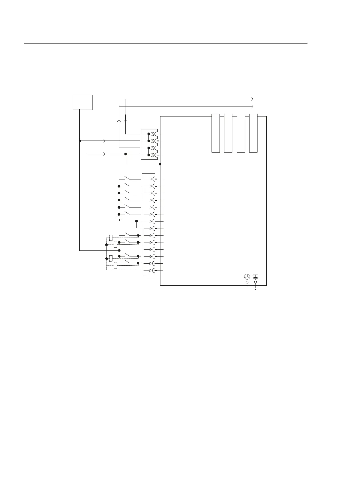
Connection example
When commissioning the system for the first time, the digital inputs/outputs are
correspondingly preassigned.
'5,9(&/L4SRUW
'5,9(&/L4SRUW
'5,9(&/L4SRUW
'5,9(&/L4SRUW
1;
0IRUWHUPLQDO
H[W
9'&
0
0
;;;;
',
',
',
',
0
','2
','2
','2
','2
0
0
9
0
0
0
0
;
;
',
',
1) Rapid inputs must be shielded.
2) Jumper open, electrical isolation for digital inputs (DI)
3) can be parameterized as either input or output
Figure 7-56 Connection example NX10.3
See also
For the pin assignment of the DRIVE-CLiQ interfaces X100 - X103, please refer to Chapter
"DRIVE-CLiQ (Page 84)".
For further information on DC voltage and standards, please see Chapter "Power supply
connection (Page 69)".
Connectable components
7.8 NX10.3
PPU
222 Manual, 01/2014, 6FC5397-2DP40-3BA3

 Loading...


