*URXQGLQJEDU
36
36
36
36
36
36
338
0&3
2SHUDWRUSDQHO
)HUURXVPDFKLQH
FRQVWUXFWLRQ
6ZLWFKLQJFDELQHW
33'
6,1$0,&6
6
34
34
36LQPRWRUFDEOH
0%
*0b
([WHUQDOSURWHFWLYHFRQGXFWRU
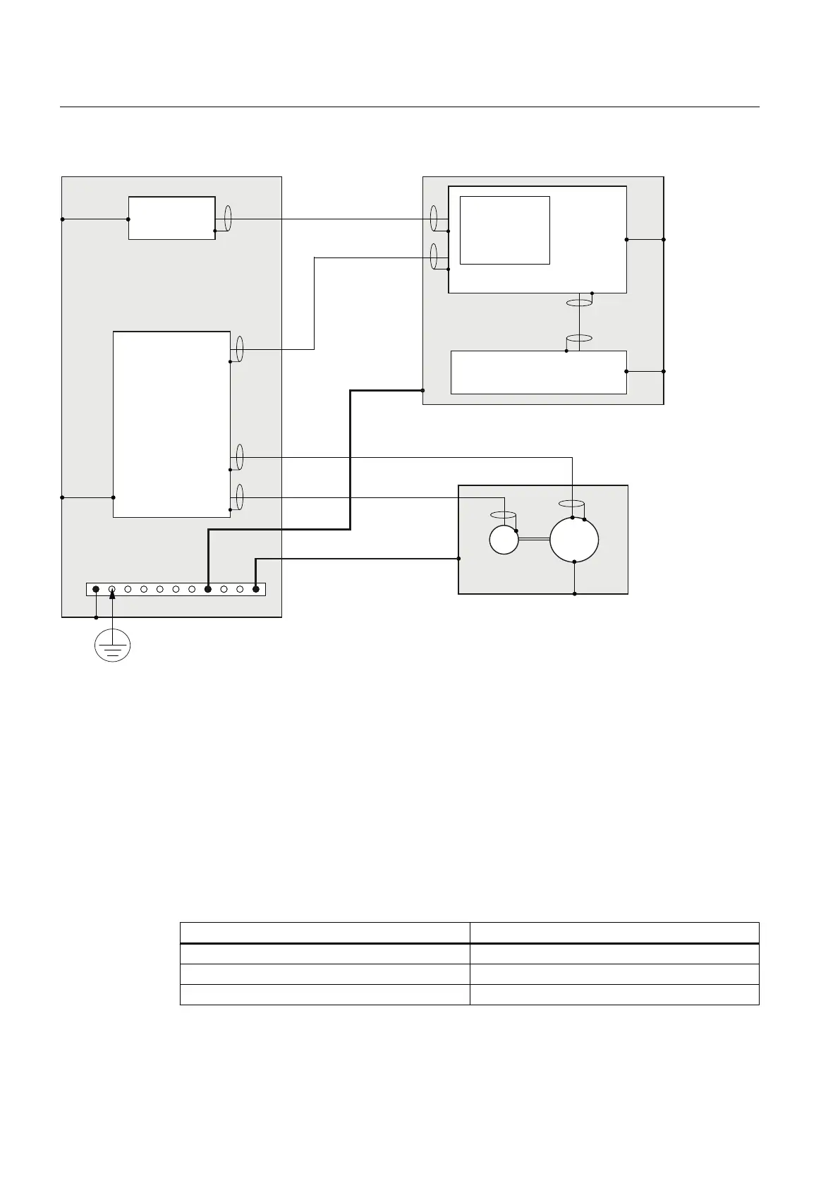
MB Shielded signal cable with reference ground
M Motor
G Encoder
PA Equipotential bonding conductor
PS Protective connection (via metal design or green-yellow protective conductors)
Figure 3-1 Grounding concept
The following rules apply for external cable cross sections:
● PA cross-section ≥ 10 mm
2
● The conductor cross-section of the external protective conductor is calculated from the
conductor cross-section of the line connection as follows:
Line connection S (mm
2
) External protective conductor min. (mm
2
)
S ≤ 16 S
16 ≤ S ≤ 35 16
S ≥ 35 S/2
Application planning
3.1 Secondary electrical conditions
PPU
36 Manual, 01/2014, 6FC5397-2DP40-3BA3

 Loading...


