OCTOBER 2005 INSTALLATION PROCEDURE 57
SIEMENS
MAINTENANCE MANUAL
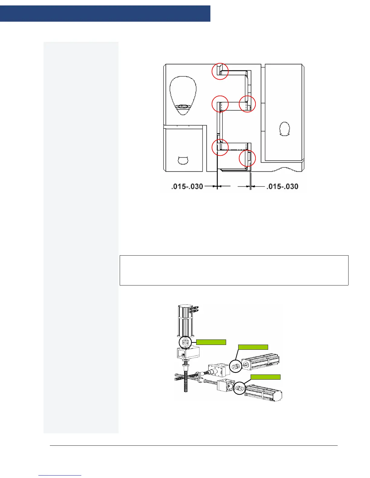
6. Install the SPIDER and set the tolerance on all 4 RAISED BOSSes to 0.015”-0.030”
from the HUB using 2 (two) 0.015”(0.381mm) and 0.030” (0.762mm) feeler gages.
Figure 3-10: Gages
7. Install Ball Screw coupler HUB on the SPIDER and set the tolerance on all 4
RAISED BOSSes to 0.015 “ - 0.030” (0.381-0.762mm) from the HUB using 2 (two)
0.015” or 0.030” feeler gages and torque coupler HUB to Ball Screw shaft using
correct torque specification.
NOTE
Verify when the coupler assembly is completely installed all 8 RAISED BOSSes must be checked
and set to 0.015” - 0.030”(0.381-0.762mm).
8. Clean marked notes from coupler assembly when installation is complete.
Figure 3-11: Motors
-AXIS 8ft
-AXIS 8ft
-AXIS 8ft

 Loading...


