Wiring
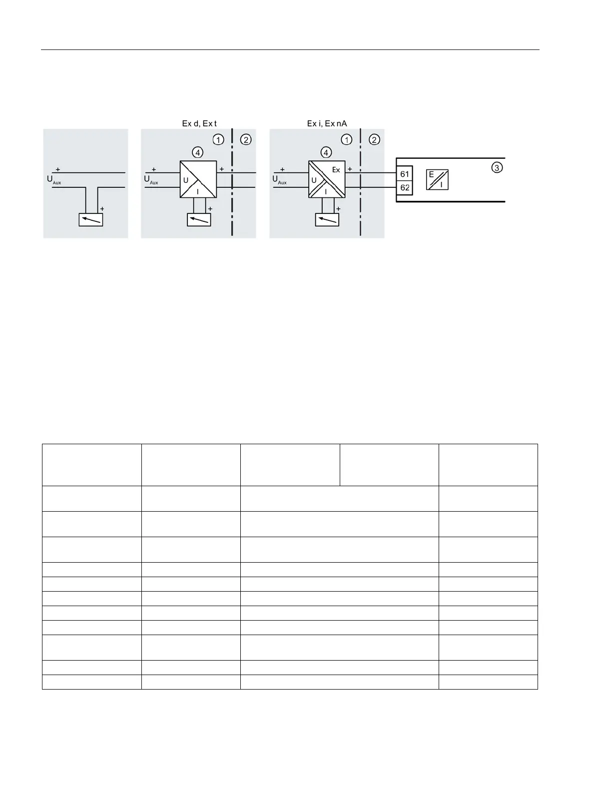
4.4 4 to 20 mA Feedback Module (Iy Module)
PS2 Troubleshooting Guide
46 Service Manual, 03/2017, A5E36661550-AA
4 to 20 mA Feedback Module (Iy Module)
✓ Typically requires a 24 V DC source
✓ For hazardous areas, consult following Feedback Module Power Specifications Chart and
local safety guidelines
✓ Unit must be initialized to transmit feedback signal
✓ Do NOT use the 4 to 20 mA MPU pair of wires for the feedback card
Connect the positive wire from the voltage source to terminal 61. Connect the positive wire
from the analog input card to terminal 62. Connect the negative of the analog input to the
negative side of the voltage source.
Feedback Module Power Specification Chart
Basic device
without Ex protection
Basic device
with Ex d explosion
protection
Basic device
with "ia" explosion
protection
Basic device with
explosion protection
"ic", "nA", "t"
DC output for position
1 current output: Ter-
2-wire connection
4 ... 20 mA, short -circuit proof
H
≤ (U
H
[V] - 12 V) / I [mA]
Temperature influence
≤ 0.1 % / 10 K (≤ 0.1 % / 18 °F

 Loading...


