Appendix A
A.4 SIPART PS2 Valve Positioner Fail-Safe Positions
PS2 Troubleshooting Guide
62 Service Manual, 03/2017, A5E36661550-AA
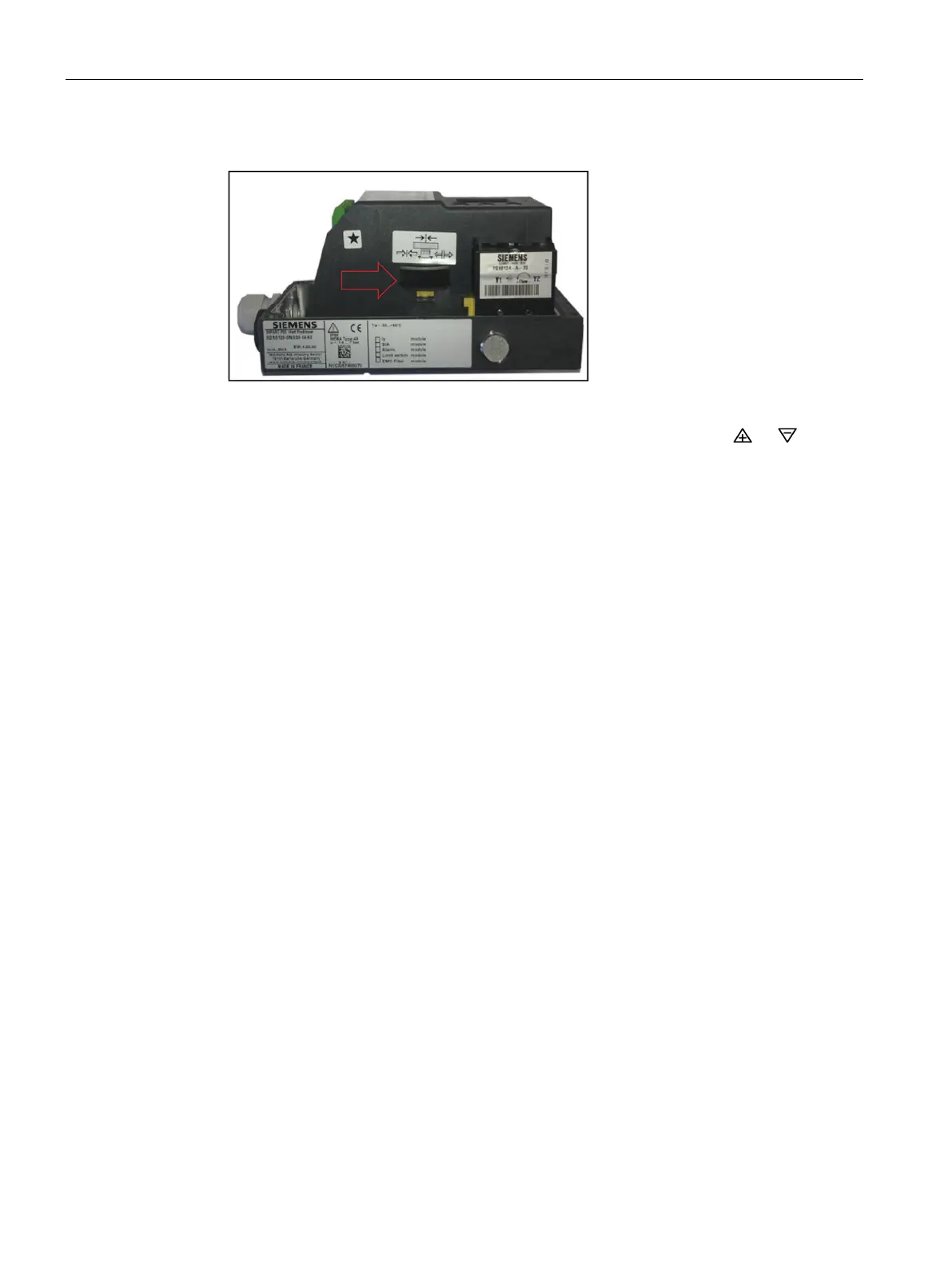
● Adjust slip clutch until number in display is within a range of: 48-52.
Figure A-2 Slip Clutch
● Move valve so the numerical number decreases, either by pressing the or button.
● Once the numerical value begins to decrease, keep button pressed to go to end-stop
position.
– If numerical value goes through zero before reaching end-stop position, see
"Determine Proper Slide Bar Setting" procedure above.
● Once at end-stop position adjust slip clutch so numerical value is within the following
numerical range: 5.8 to 6.8.
● Using other push button drive valve to other end-stop position.
– Numerical value should be less than 95, if not:
○ See "Determine Proper Slide Bar Setting" section above, or…
○ For linear valves, there can be too much mechanical travel on feedback arm.
Mechanical feedback travel should not exceed 100° rotation. If necessary secure
feedback pin further away from positioner’s input shaft or…
○ Actuator end-stops are set too wide, narrow actuator end-stop travel.
Unit is now ready for intiialization procedure. See Initialization Procedure.
SIPART PS2 Valve Positioner Fail-Safe Positions
When designing a process loop containing a valve and valve positioner, it is wise to consider
the position the valve should go to, i. e., the valve’s fail-safe position, in response to each
potential system failure. Often valve position during a system failure is not considered until
an actual failure occurs and the valve goes to an unexpected position. This can result in a
hazardous situation for plant personnel, damage to process equipment, or loss of product or
product constituents. Valve fail-safe position is implemented when piping a positioner to a
valve actuator.
Figure A-3 Reaction to failure of auxiliary powers
below shows the resulting actuator/valve
positions for various positioner-to-actuator piping connections and with loss of input signal
and/or supply air.

 Loading...


