Appendix A
A.2 Initialization Procedure
PS2 Troubleshooting Guide
54 Service Manual, 03/2017, A5E36661550-AA
6. Using the and buttons, scroll to appropriate actuator type. See description below.
– turn/-turn: Use this setting for a part-turn actuator with a directly mounted positioner.
– WAY/-WAY: Use this setting for a linear actuator with a carrier pin mounted on the
lever.
– FWAY/-FWAY: Use this setting for a linear actuator with a carrier pin mounted on the
actuator spindle. (Available with Profibus and Foundation Fieldbus, 2016).
– LWAY/-LWAY: Use this setting for an external linear potentiometer on a linear
actuator.
– ncSt/-ncSt: Use this setting for an NCS sensor (6DR4004-.N.10 and -.N.40) on a part-
time actuator and for internal NCS module.
– ncSL/-ncSL: Use this setting for an NCS sensor (6DR4004-.N.20) on a linear actuator
for strokes < 14 mm (0.55 inch).
– ncSLL/-ncLL: Use this setting for an NCS sensor (6DR4004-.N.30) on a linear actuator
for strokes > 14 mm (0.55 inch) and for an internal NCS module.
In the case of actuators with inverted direction of action, use the settings with the minus
sign, e. g. -turn.
Meaning of actuator with normal direction of action:
– Part-turn/rotary actuator closes when the drive shaft, positioner shaft or magnet of the
NCS sensor rotates in the clockwise direction.
– Linear actuator closes when the actuator spindle rotates downwards and the
positioner shaft or magnet of the NCS sensor rotates in the anti-clockwise direction.
Meaning for actuator with inverted direction of action:
– Part-turn/rotary actuator closes when the drive shaft, positioner shaft or magnet of the
NCS sensor rotates in the anti-clockwise direction.
– Linear actuator closes when the actuator spindle rotates downwards and the
positioner shaft or magnet of the NCS sensor rotates in the clockwise direction.
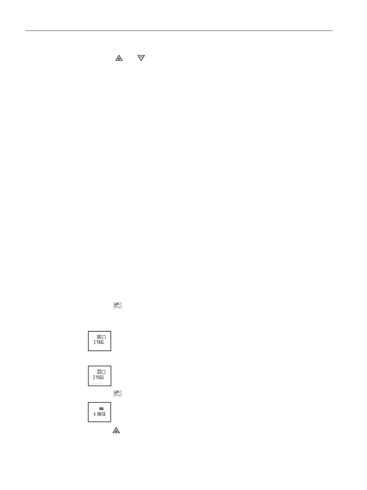
7. Push the
button once to move to parameter 2. Set appropriate value as per actuator;
FOR ROTARY ACTUATORS AND FOR LINEAR ACTUATORS greater than 1inch/25
mm
FOR LINEAR ACTUATORS with strokes less than 1inch/25 mm
8. Push the
button until parameter 4 is reached. The display will read;
9. Hold the
button until the calibration starts, then release.

 Loading...


