Mounting and Commissioning
3.1 Mounting and Connections
SIPROTEC, 7RW80, Manual
C53000-G1140-C233-1, Release date 10.2010
148
Installation or Replacement of the Ethernet Interface Module
The following requirement must be fulfilled:
There is no SIPROTEC 4 communication module mounted yet. Otherwise, this has to be removed before ac-
tually installing the Ethernet interface module (see below).
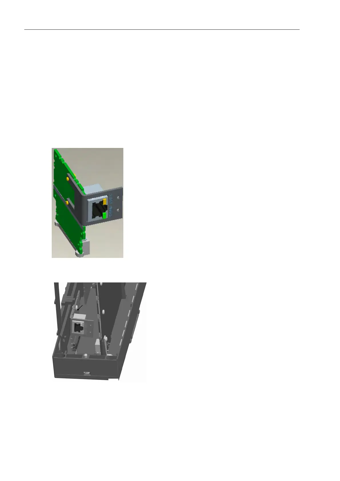
The Ethernet interface module is inserted in the respective slot, most suitably from the open bottom, i.e. above
the back of the battery case. A supporting frame is placed over the modular plug. The narrow spacer lies at
edge of the printed circuit board. The module is attached to the 50-pole plug connector of the CPU module
slightly inclined to the basic I/O board. The supporting plate is slightly pulled outwards in this area. The module
can now be inserted vertically up to the stop. Then, the supporting plate is pressed against in the area of the
locking latch until the upper edge of the printed circuit board of the Ethernet interface module snaps into the
locking latch.
Figure 3-5 Ethernet interface with support frame
Figure 3-6 Installation of the Ethernet interface
Now, a SIPROTEC 4 communication module can be installed (see Section Installation or Replacement of a
SIPROTEC 4 Communication Module). Otherwise, the device can be reassembled again (see Section Reas-
sembly).

 Loading...


