Functions
2.7 SYNCHROCHECK 25
SIPROTEC, 7RW80, Manual
C53000-G1140-C233-1, Release date 10.2010
94
With External Control
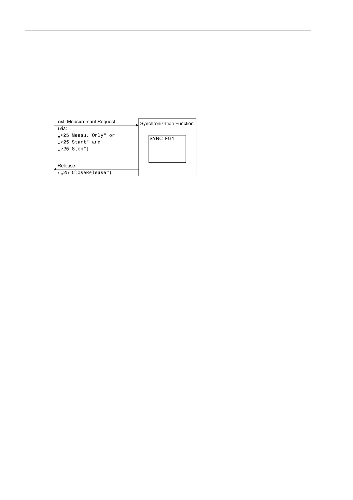
As another option, the synchrocheck function can be activated via external measurement requests. The syn-
chrocheck function can be started via binary input using measurement request („>25 Sync requ.“ or pulse-
like start and stop signals „>25 Start“, „>25 Stop“). Having completed the check, the synchrocheck func-
tion issues the release message („25 CloseRelease“) (see Figure ). Measurement is terminated as soon
as the measurement request is reset via the binary input. In this case, there is no need to configure a control
device to be synchronized.
Figure 2-24 Interaction of synchrocheck function and external control
2.7.6 Setting Notes
General
The synchronization function can only operate if 25 Function 1 with SYNCHROCHECK was enabled at
address 161 during configuration of the functional scope (see Section 2.1.1.2). If this function is not required,
then Disabled is set.
While setting the power system data 1 (see Section 2.1.3.2) the device was already provided with data relevant
for the measured values and the operating principle of the synchronization function. This concerns the following
parameters:
202 Vnom PRIMARY primary nominal voltage of the voltage transformers V
1
(phase-to-phase) in kV;
203 Vnom SECONDARY secondary nominal voltage of the voltage transformers V
1
(phase-to-phase) in V;
213 VT Connect. 3ph specifies how the voltage transformers are connected.
When using the synchronization function the setting Vab, Vbc, VSyn is used if two phase-to-phase voltages
are open delta-connected to the device. You can use any phase-to-phase voltage as the reference voltage
V
SYN
.
Use the setting Vph-g, VSyn if only phase-to-ground voltages are available. One of these voltages is con-
nected to the first voltage transformer; the reference voltage V
SYN
is connected to the third voltage transformer.
V
A
a the first voltage transformer and V
B
at the third voltage transformer must belong to the same voltage type
(VAN or VBN or VCN).
Connection examples are given under side heading „Voltage Connections“ and in the Appendix A.3.
If you have set Vab, Vbc, VSyn or Vph-g, VSyn, the zero sequence voltage can not be determined. Table
2-1 in the chapter 2.1.3.2 provides information about the consequences of the different voltage connection
types.
The operating range of the synchronization function (f
Nom
± 3 Hz) refers to the nominal frequency of the power
system, address 214 Rated Frequency.
The corresponding messages of the SYNC function group are pre-allocated for IEC 60870–5–103 (VDEW).
Selecting the SYNC function group in DIGSI opens a dialog box with tabs in which the individual parameters
for synchronization can be set.

 Loading...


