Functions
2.2 Voltage Protection 27, 59
SIPROTEC, 7RW80, Manual
C53000-G1140-C233-1, Release date 10.2010
43
2.2.3 Undervoltage Protection 27
Undervoltage protection consists of three elements (27-1 PICKUP, 27-2 PICKUP, 27 Vp<). Therefore, trip-
ping can be time-graded depending on how severe voltage collapses are. Voltage thresholds and time delays
can be set individually for both elements 27-1 PICKUP and 27-2 PICKUP.
Additionally the element 27 Vp< allows the definition of a user defined tripping curve with 20 value pairs (volt-
age/time). Parameterization is done via DIGSI.
For both under-voltage elements 27-1 PICKUP, 27-2 PICKUP the dropout ratio (= V
dropout
/V
pickup
) can be
parameterized.
A parameter is set to specify, whether the measured values of all phases or only phases with the lowest value
for monitoring are being used.
The undervoltage protection works in an additional frequency range. This ensures that the protective function
is preserved even when it is applied e.g. as motor protection in context with decelerating motors. However, the
r.m.s. value of the positive-sequence voltage component is considered too small when severe frequency de-
viations exist. This function therefore exhibits an overfunction.
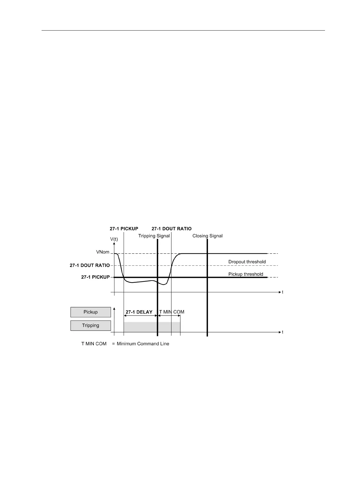
Figure 2-3 shows a typical voltage profile during a fault for source side connection of the voltage transformers.
After the voltage has decreased below the pickup setting, tripping is initiated after time delay 27-1 DELAY. As
long as the voltage remains below the drop out setting, reclosing is blocked. Only after the fault has been
cleared, i.e. when the voltage increases above the drop out level, the element drops out and allows reclosing
of the circuit breaker.
Figure 2-3 Typical fault profile for supply-side connection of the voltage transformers.
The following Figure shows the logic diagram of the undervoltage protection function.
 Loading...


