Functions
2.1 General
SIPROTEC, 7RW80, Manual
C53000-G1140-C233-1, Release date 10.2010
35
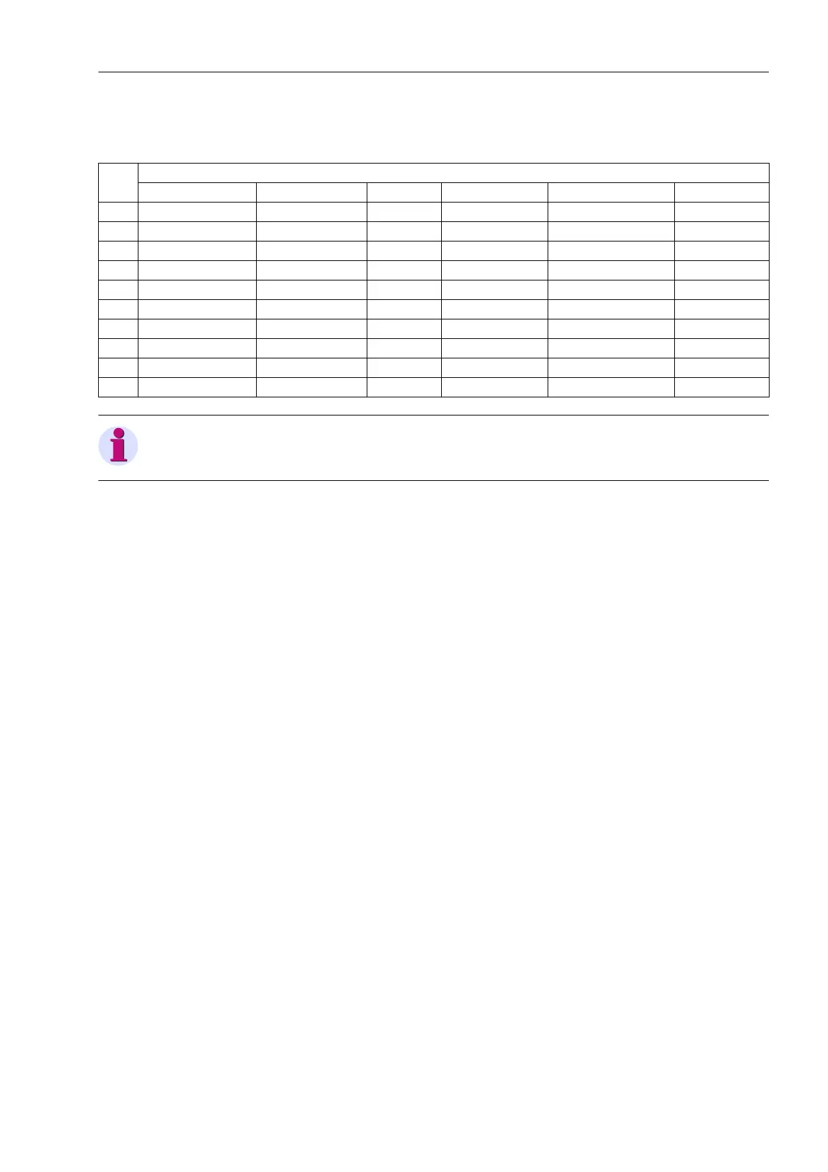
Depending on the selected type of connection of the voltage transformers (address 213 VT Connect. 3ph),
the following measured values are recorded in the fault record:
Note
The signals used for the binary tracks can be allocated in DIGSI.
2.1.4.2 Setting Notes
Specifications
Fault recording (waveform capture) will only take place if address 104 OSC. FAULT REC. is set to Enabled.
Other settings pertaining to fault recording (waveform capture) are found in the OSC. FAULT REC. submenu
of the SETTINGS menu. Waveform capture makes a distinction between the trigger instant for an oscillographic
record and the criterion to save the record (address 401 WAVEFORMTRIGGER). Normally, the trigger is the
pickup of a protection element, i.e. the time 0 is defined as the instant the first protection function picks up. The
criterion for saving may be both the device pickup (Save w. Pickup) or the device trip (Save w. TRIP). A
trip command issued by the device can also be used as trigger instant (Start w. TRIP), in this case it is also
the saving criterion.
Recording of an oscillographic fault record starts with the pickup by a protective function and ends with the
dropout of the last pickup of a protective function. Usually this is also the extent of a fault recording (address
402 WAVEFORM DATA = Fault event). If automatic reclosing is performed by external equipments, the entire
system fault — with several reclosing attempts if necessary — can be recorded until the fault has been cleared
for good (address 402 WAVEFORM DATA = Pow.Sys.Flt.). This facilitates the representation of the entire
system fault history, but also consumes storage capacity during the auto-reclosure dead time(s).
The actual storage time encompasses the pre-fault time PRE. TRIG. TIME (address 404) ahead of the ref-
erence instant, the normal recording time and the post-fault time POST REC. TIME (address 405) after the
storage criterion has reset. The maximum recording duration to each fault (MAX. LENGTH) is entered in
address 403. Recording per fault must not exceed 5 seconds. A total of 8 records can be saved. However, the
total length of time of all fault records in the buffer must not exceed 18 seconds.
An oscillographic record can be triggered by a status change of a binary input, or from a PC via the operator
interface. Storage is then triggered dynamically. The length of the fault recording is set in address 406 BinIn
CAPT.TIME (but not longer than MAX. LENGTH, address 403). Pre-fault and post-fault times will add to this.
If the binary input time is set to ∞, the length of the record equals the time that the binary input is activated
(static), but not longer than the MAX. LENGTH (address 403).
Voltage connection
Van, Vbn, Vcn Vab, Vbc, VGnd Vab, Vbc Vab, Vbc, Vx Vab, Vbc, VSyn Vph-g, VSyn
V
AB
yes yes yes yes yes
V
BC
yes yes yes yes yes
V
CA
yes yes yes yes yes
V
A
yes yes
V
B
yes yes
V
C
yes yes
V yes
V
0
yes yes
V
SYN
yes yes
V
x
yes
 Loading...


