Mounting and Commissioning
3.3 Commissioning
SIPROTEC, 7RW80, Manual
C53000-G1140-C233-1, Release date 10.2010
166
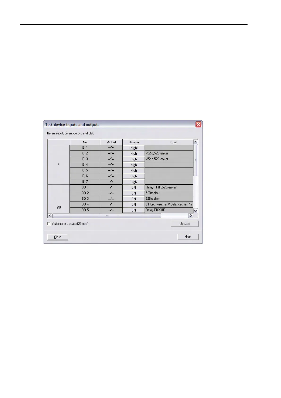
Structure of the Test Dialog Box
The dialog box is classified into three groups: BI for binary inputs, REL for output relays, and LED for light-
emitting diodes. On the left of each of these groups is an accordingly labelled button. By double-clicking a
button, information regarding the associated group can be shown or hidden.
In the column Status the present (physical) state of the hardware component is displayed. Indication is made
by symbols. The physical actual states of the binary inputs and outputs are indicated by an open or closed
switch symbol, the LEDs by a dark or illuminated LED symbol.
The opposite state of each element is displayed in the column Scheduled. The display is made in plain text.
The right-most column indicates the commands or messages that are configured (masked) to the hardware
components.
Figure 3-22 Testing the inputs and outputs
Changing the Operating State
To change the status of a hardware component, click on the associated button in the Scheduled column.
Password No. 6 (if activated during configuration) will be requested before the first hardware modification is
allowed. After entry of the correct password a status change will be executed. Further status changes remain
possible while the dialog box is open.
Test of the Output Relays
Each individual output relay can be energized for checking the wiring between the output relay of the 7RW80
and the substation, without having to generate the message assigned to it. As soon as the first change of state
for any one of the output relays is initiated, all output relays are separated from the internal device functions
and can only be operated by the hardware test function. This for example means that a switching command
coming from a protection function or a control command from the operator panel to an output relay cannot be
executed.

 Loading...


