Functions
2.4 Load Restoration
SIPROTEC, 7RW80, Manual
C53000-G1140-C233-1, Release date 10.2010
63
During the pickup time of LR2 the network frequency drops briefly below the pickup threshold, but not below
the dropout threshold of LR2. This stops the pickup of load restoration element LR2, but does not reset this
procedure in the dropout delay time. When the frequency reaches the pickup threshold of LR2 (49.5 Hz) again,
the pickup time of LR2 will be continued.
When pickup time has expired, the element LR2 initiates the load restoration.
Subsequently the pickup of load restoration LR1 is processed. When the pickup frequency of LR1 (49.75 Hz)
is reached, LR1 picks up. LR1 initiates the restoration when pickup time has expired.
When the monitoring time has expired (address 5501 LR t Monitor), the message 17335 „LR
Successful“ is displayed (not shown in the picture).
Assignments to Frequency Elements
At addresses 5528 to 5531, 5548 to 5551, 5568 to 5571 and 5588 to 5591 you may assign the underfre-
quency elements, which trigger the load restoration element (when tripping).
Monitoring
At address 5501 LR t Monitor you may configure the monitoring time of the load restoration cycles.
At address 5502 LR Max. Cycles you may configure the maximum number of restoration cycles of the load
restoration.
Load restoration across several devices
The Load Restoration can be applied across several 7RW80 devices. The Load Restoration across several
devices can be coordinated using the CFC.
To ensure the correct restoration sequence between several 7RW80 devices you must connect the output
17338 „LR Process“ of the first restoring device with the input 17332 „>LR Process“ of the other devices.
Furthermore you have to configure the user defined messages „LR txBlock“ and „LR txBreak “.
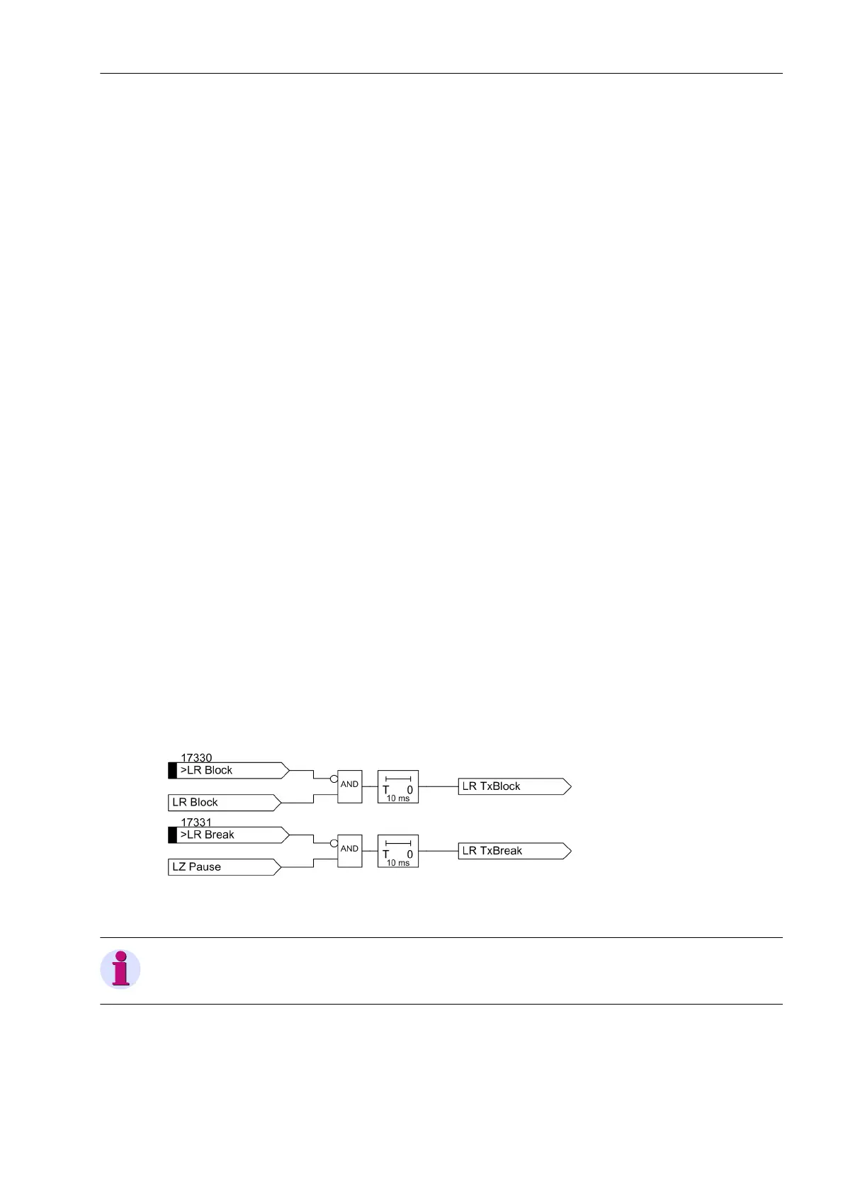
The output messages „LR txBlock“ and „LR txBreak “ are connected to the according binary inputs of
the opposite devices 17330 „>LR Block“ and 17331 „>LR Break“.
In the CFC the following logic is applied:
Figure 2-12 Load Restoration across several devices - CFC-Logic
Note
Use the fast CFC task level PLC1_BEARB.

 Loading...


