Functions
2.7 SYNCHROCHECK 25
SIPROTEC, 7RW80, Manual
C53000-G1140-C233-1, Release date 10.2010
96
Power System Data
The system related data for the synchronization function are set at addresses 6121 to 6125.
The parameter Balancing V1/V2 (address 6121) can be set to account for different VT ratios of the two
parts of the power system (see example in Figure ).
If a transformer is located between the system parts to be synchronized, its vector group can be accounted for
by angle adjustment so that no external adjusting measures are required. Parameter ANGLE ADJUSTM. (ad-
dress 6122) is used to this end.
The phase angle from V
1
to V
2
is evaluated positively.
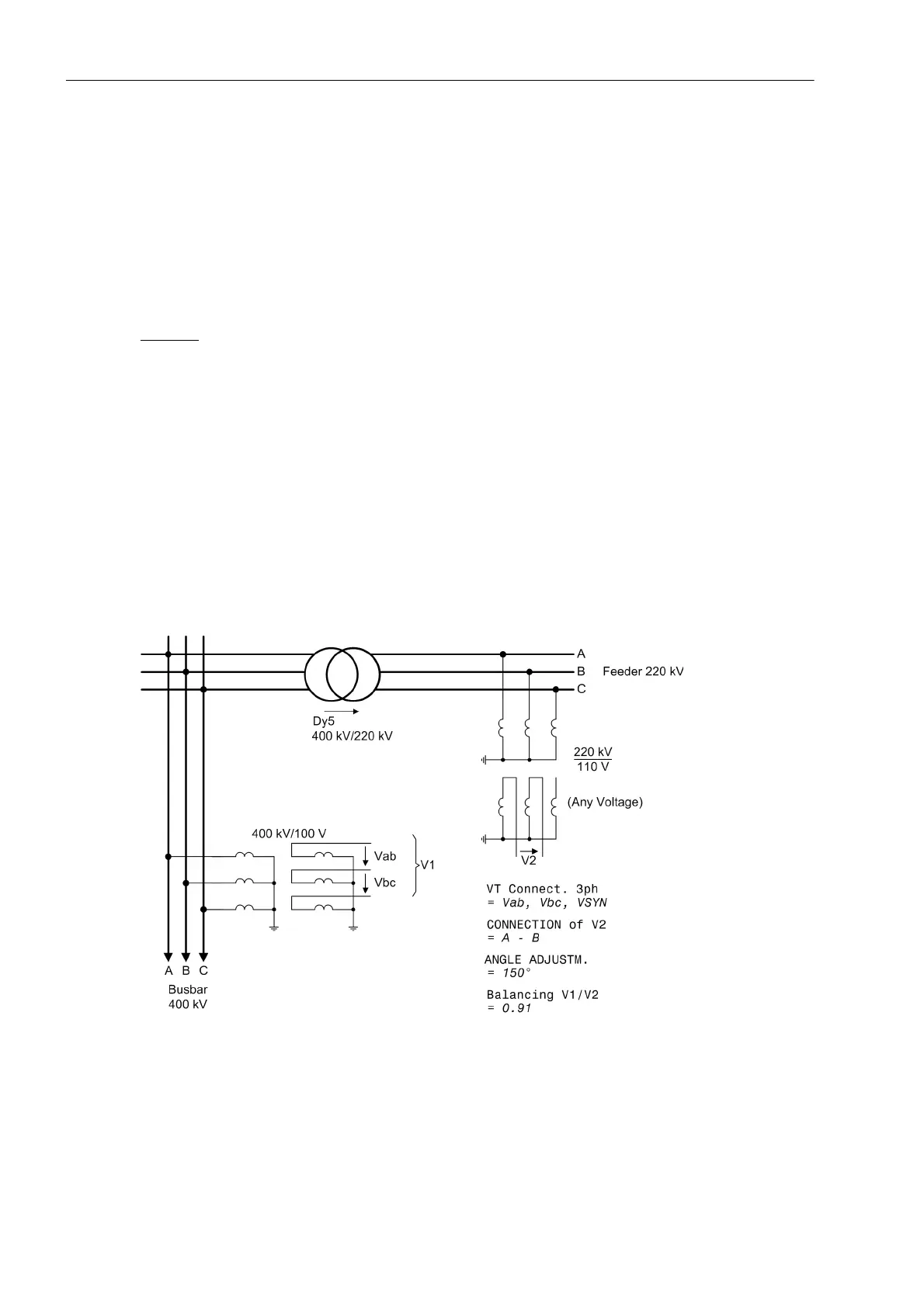
Example: (see also Figure ):
Busbar 400 kV primary; 100 V secondary
Feeder 220 kV primary; 110 V secondary
Transformer 400 kV/220 kV; vector group Dy(n)5
The transformer vector group is defined from the high side to the low side. In the example, the reference voltage
transformers (V
1
) are the ones of the transformer high side, i.e. the setting angle is 5 x 30° (according to vector
group), that is 150°:
Address 6122 ANGLE ADJUSTM. = 150°.
The reference voltage transformers supply 100 V secondary for primary operation at nominal value while the
feeder transformer supplies 110 V secondary. Therefore, this difference must be balanced:
Address 6121 Balancing V1/V2 = 100 V/110 V = 0.91.
Figure 2-25 Busbar voltage measured across the transformer

 Loading...


