Requirements
Setup of the SINAMICS S120 Training Case
SINAMICS S120 at Technology CPU Entry ID: 21767896
V1.0 Edition 10/28/05 8/58
Copyright © Siemens AG 2005 All rights reserved
SINAMICS S120 und Technologie-CPU V2.0-SP1__05-10-28_13-20_e.doc
The wiring shown above refers to the SINAMICS S120 training case.
Alternatively to the wiring via the digital inputs of the TB30 terminal board,
the wiring can also be performed directly to the digital inputs of the CU320
control unit.
Deactivating feedback at the SINAMICS S120 training case
To take into account the special operating conditions of the smart line
module (SLM) at the SINAMICS S120 training case, the feedback of the
smart line module was deactivated in the training case.
This ensures that no energy is fed back to the network from the DC-link.
However, a braking module and a braking resistor are not required at the
SINAMICS S120 training case, since the connected motors are operated
with small load and consequently only little braking energy has to be
processed by the smart line module.
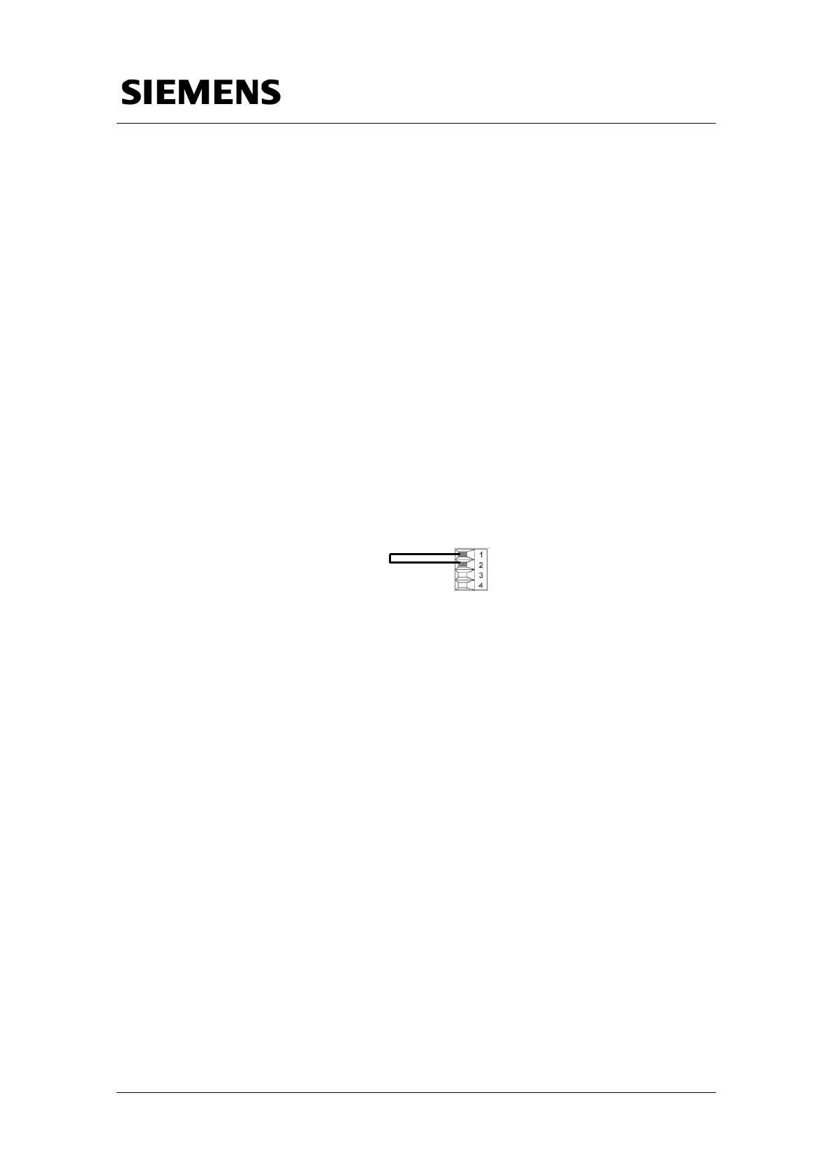
To deactivate the feedback at the smart line module, it is required to install
a jumper between the terminals X22.1 and X22.2 of the module.
Figure 1-3 Jumper for deactivation of the feedback at SLM
X22
 Loading...


