Requirements
Setup of the SINAMICS S120 Training Case
SINAMICS S120 at Technology CPU Entry ID: 21767896
V1.0 Edition 10/28/05 7/58
Copyright © Siemens AG 2005 All rights reserved
SINAMICS S120 und Technologie-CPU V2.0-SP1__05-10-28_13-20_e.doc
Smart line modules do not feature a DRIVE-CLiQ interface; for this reason,
port X100 at the CU320 control unit (as at the SINAMICS S120 training
case) is not used in this case.
1.4 Hardware wiring of the components
Since the smart line module does not feature a DRIVE-CLiQ interface for
connection to the CU320 control unit, it is required to connect the signals of
this module to the control unit via the hardware wiring.
The following signals are to be wired between the smart line module (SLM)
and the CU320 control unit; interfacing at the SINAMICS S120 training
case is performed via the TB30 terminal board:
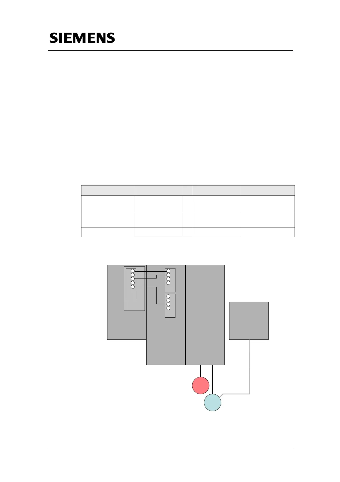
Table 1-2 Hardware wiring between smart line module and control unit
Signal SLM TB30 Comment
SLM Ready DO: X21.1
Î
DI: X481.1
SLM ready for
operation
Overtemperature
Prewarning
DO: X21.2
Î
DI: X481.3
Prewarning
overtemperature
Reset DI: X22.3
Í
DO: X481.5 Reset failures
Figure 1-2 Hardware wiring at the SINAMICS S120 training case
Smart line
module
(6SL3130-6AE15-0AA0)
CU 320
(6SL3040-0MA00-0AA1)
Double
motor module
(6SL3120-2TE13-0AA0)
Motor
&
encoder
1
Motor
&
encoder
2
SMC 20
(6SL3055-0AA00-5BA1)
-X1 -X2
-X520
(1FK7022-5AK71-1LG0)
(1FK7022-5AK71-1AG3)
TB30
-X481
1
2
3
4
5
…
-X21
1
2
3
4
-X22
1
2
3
4
Ready
Pre Warning
Reset
 Loading...


