9
SIVACON S8 Planning Principles – SIVACON S8 – System overview
2
3
4
5
6
7
8
9
10
11
1
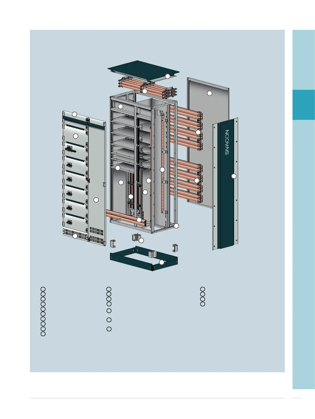
Fig. 2/1: Cubicle design of SIVACON S8
1
2
3
4
5
6
7
8
9
10
11
12
13
14
15
16
17
18
19
1 11 18
2 12 19
3 13 20
4 14 21
5
6
7
8
9
10
20
21
Enclosure Busbars Internal separation
Roof plate Main busbar (L1... L3, N) – top Device compartment/busbar compartment
Rear panel Main busbar (L1... L3, N) – rear top Cubicle to cubicle
Design side panel Main busbar (L1... L3, N) – rear bottom Compartment to compartment
Frame Main busbar (PE) – bottom Cross-wiring compartment
Base cover
Vertical distribution busbar system (L1... L3, N)
device compartment
Base
Vertical distribution busbar (PE)
cable connection compartment
Ventilated base compartment cover
Vertical distribution busbar (N)
cable connection compartment
Ventilated cubicle door
Compartment door
Head room door
15
16
17

 Loading...


