16
SIVACON S8 Planning Principles – SIVACON S8 – System overview
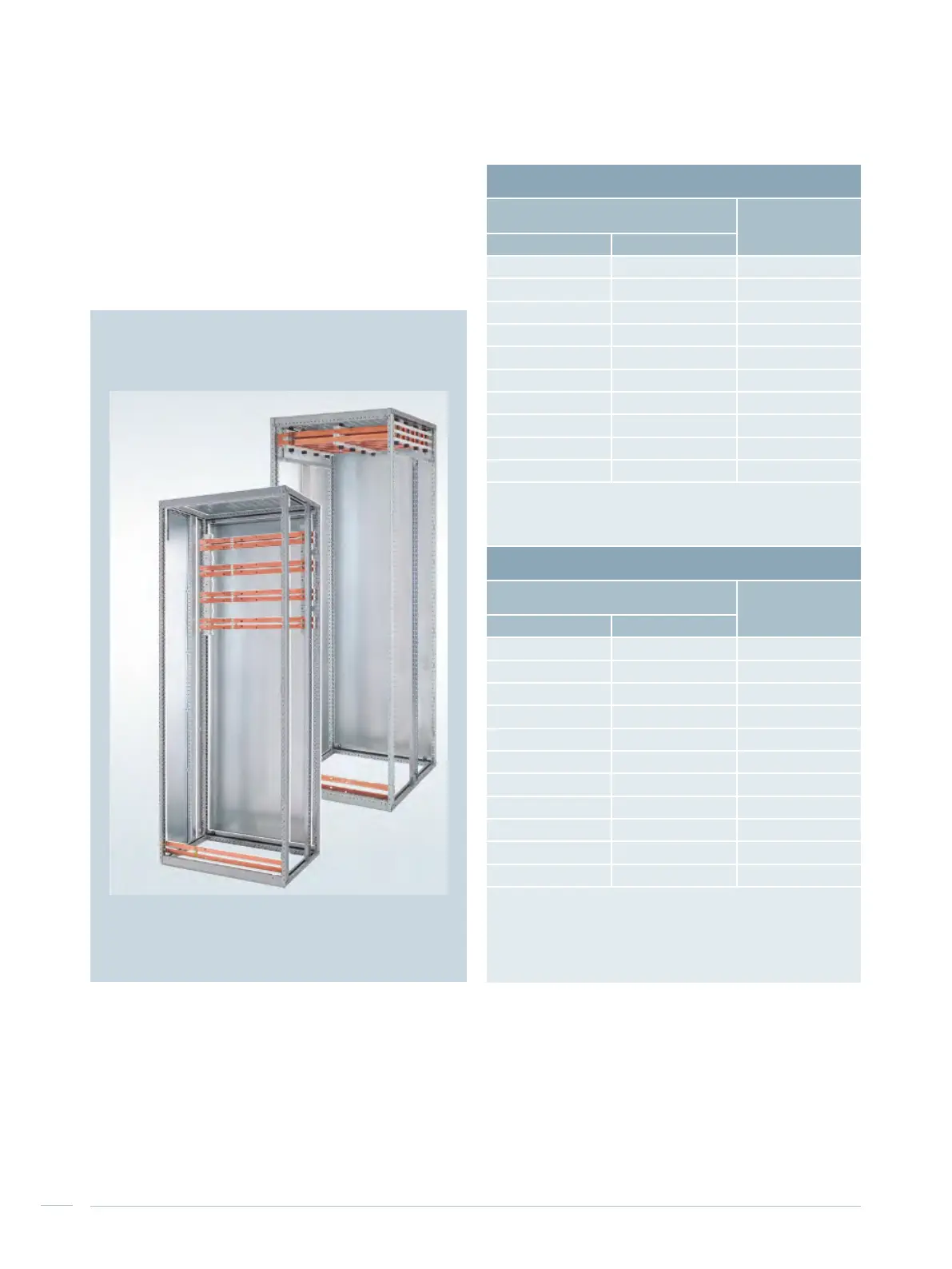
2.3 Main busbar, horizontal
Tab. 2/7 lists the rating data for the two possibilities how to
position the main busbar – top or rear – (Fig. 2/4). Chapter
10 describes how ambient temperatures must be observed
in respect of the current carrying capacity.
Tab. 2/7: Rating of the main busbar
Fig. 2/4: Variable busbar position for SIVACON S8
Top busbar position
Rated current I
n
at 35 °C ambient
temperature
Rated short-time
withstand current
I
cw
(1 s)
Ventilated Non-ventilated
1,190 A 965 A 35 kA
1,630 A 1,310 A 50 kA
1,920 A 1,480 A 65 kA
2,470 A 1,870 A 85 kA
3,010 A 2,250 A 100 kA
3,270 A 2,450 A 100 kA
3,700 A
1)
3,000 A
1)
100 kA
4,660 A
1)
3,680 A
1)
100 kA
5,620 A
1)
4,360 A
1)
150 kA
6,300 A
1)
4,980 A
1)
150 kA
1)
If circuit-breakers with a very high power loss are used, the
following correction factors must be applied:
3WL1350: 0.95
3WL1363: 0.88
Rear busbar position
1)
Rated current I
n
at 35 °C ambient
temperature
Rated short-time
withstand current
I
cw
(1 s)
Ventilated Non-ventilated
1,280 A 1,160 A 50 kA
1,630 A 1,400 A 65 kA
2,200 A 1,800 A 65 kA
2,520 A 2,010 A 85 kA
2,830 A 2,210 A 100 kA
3,170 A 2,490 A 100 kA
4,000 A 3,160 A 100 kA
4,910 A
2)
3,730 A
2)
100 kA
5,340 A
2)
4,080 A
2)
100 kA
5,780 A
2)
4,440 A
2)
100 kA
7,010 A
2)
5,440 A
2)
150 kA
1)
When operating two systems per cubicle at the same time
(busbar position rear top and rear bottom),
a reduction factor has to be considered::
for ventilated boards: 0,94
for unventilated boards: 0,98
2)
Busbar position rear top or rear bottom

 Loading...


